


3
Remote Control Switchers
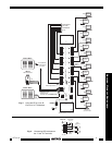
1 2 3 4 5 6
ON
1
Controller &
Address
Switches
ON (1)
OFF (0)
Factory Installed
Jumper
IR Receiver
Input Connector
on RT16-10
IR RCVR
INPUT
+12 G G
S
S
Fig. 4
1234
5678
9101112
13 14 15 16
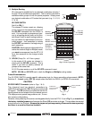
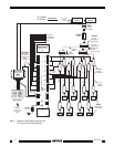
GP-ON GP-OFF
C
GP-ON
GP-OFF
Routing
Commands
(1 through 16)
80 48 10 90 01
00 C0 50 D0 41
40 A0 30 B0 21
20 E0 70 F0 61
60 88 18 98 09
08 A8 38 B8 29
28 E8 78 F8 69
68 C8 58 D8 49
E1 89 C9 A9 E9
71 19 59 39 79
F1 99 D9 B9 F9
RC68+
Code Group
Numbers
(on face of
each button)
Place the
"C" Overlay
on the RC68+
2. Multiple Routing
IR routes can be established to any desired combination of ports (1
through 16) for simultaneous operation. This is useful if you wish to
address smaller groups of units for special purposes. Simply press
any desired combination of IR routes that you want (e.g., 2, 4, 5, 8,
11 & 16).
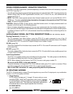
ID CODE SWITCH
Set #1 to ON (1)
The chosen IR routes remain on, allowing
you to control just the selected devices until
the GP-OFF command from the RC68+ is
sent. You may make up sequences (mac-
ros) in a learning device (such as the Xan-
tech Smart Pads) for each routing combina-
tion you desire for rapid access to the con-
trolled groups. Just remember to include
the GP-OFF command at the beginning of
each sequence.
CAUTION:
Each time you adjust switch 1 to
select the desired Single or Multiple mode,
you must remove power from the RT16-10
for a few moments for the change to take
effect.
3. GP-ON (Group On - all 16 as a group)
In this mode all 16 routes are chosen in-
stantly with the GP-ON command. This is
useful if you wish to quickly address all
groups at the same time.
All 16 IR routes remain on until the GP-OFF command is sent.
NOTE: GP-ON and GP-OFF work in both the Single and Multiple routing modes.
Future Enahncements
The ID CODE SWITCH permits specific addressing logic for future cascading enhancements. NOTE:
Switches 2 ~ 6 must remain OFF (0) except when used with the RC68+ (or RC68) IR commands.
CAUTION
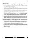
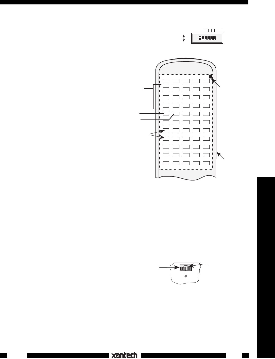
IR RCVR INPUT Connector (refer to Figs. 1 & 4)
This 4-terminal input has electrical connections for
+12V, G (chassis ground), GS (IR signal ground) and S
(IR signal). The GS terminal is provided so that the IR
signal ground can be isolated from the chassis ground.
This helps prevent ground loop problems, etc., in com-
plex system configurations.
However, when powering IR receivers and keypads directly from the RT16-10, as in Fig. 5, you
must leave
the factory installed jumper
wired between the G and GS terminals as shown. This provides the needed
ground return for the IR signal.
Remove the jumper only when powering IR source devices separately
and there is a need for electrical isolation
.
Fig. 3 RC68 Programmer
RT16-10