


4
INSTALLATION
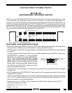
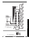
Fig. 5 illustrates a typical application where an RT16-10 is used to route IR control signals to 15 TV monitors.
1. For this example, it is assumed that Single Routing with Group ON and OFF is required.
2. Since only one RT16-10 is used in the system, the factory preset Code Group 70 can be used. The
RC68+ Programmer is set to the same number.
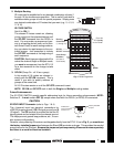
3. The RC68+ commands 1 through 15 (see Fig. 3) will establish an IR route to each TV individually. The
Group On command will route to all 15 TV's simultaneously.
Subsequent IR commands specific to the TV's, such as channel Up/Down, then operate the functions
of the TV or TV's addressed.
4. In this system, the RC68+ codes are "taught" to a Xantech URC type Learning Remote for use with
the 780-10 J-box IR Receiver or to a Xantech Smart Pad. Other learning devices may be used provided
they are capable of learning and outputting the RC68+ codes, with carrier, to the RT16-10.
5. When programming, begin by assigning 17 keys for the RC68+ commands to a keypad or learning
device.
Commands 1 through 15 for individual routing and 16 & 17 for the Group On and Group OFF
commands. Next, assign the keys for the TV function commands, such as channel Up/Down.
6. Teach the commands into the assigned keys, following the instructions that come with the learning
device. On the URC and the Smart Pad
3
, all these commands could go into one bank.
7. The "I and G" terminals on each of the output terminal jacks are provided so that LED indicators, placed
near each TV Monitor (if desired) will give a visual indication of the currently controlled Monitor. Refer
to Fig. 6. Use LED's with an operating current rating of 20 to 25 mA.
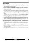
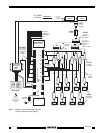
Fig. 7 shows an alternate installation method. In this example, the coaxial cables are used to carry the IR
control signals to the emitters on 15 TV monitors, along with the RF signals. This eliminates the need to
run 2-conductor wire to each TV.
1. Using the Xantech "Xtra Link™" principle, CPL10 IR/RF Couplers are used to inject the IR signals onto
the coaxial cable at the "head end" and extract them at the other end to drive the emitters at each TV
monitor.
2. Fig. 7 also illustrates the use of a Xantech 789-44 Connecting Block for control of the TV/Video sources
as well as the TV Monitors. Note that the 789-44 is powered from the RT16-10.
3. A Channel Plus DA500 RF Amp in the RF system overcomes the RF signal losses of the RF splitters
and the long cable lengths.
4. NOTE: Be sure the long cable lengths between the CPL10 Couplers are connected to the terminals
marked RF/IR as shown!
RT16-10