


Section 3. Operation
Remote Programming
20 Operating Manual for APG for XT/HPD Series Power Supply
3. Vary the external voltage from 0-10Vdc to cause the power supply output to vary
from 0-100% of rated output voltage. You may set the power supply's output
current limit using another source or the front panel current limit control.
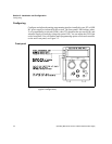
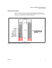
Note:Access the zero offset adjustment through the rear panel hole labelled
OFFSET. Access the full scale calibration adjustment through the rear panel hole
labelled RANGE. See Figure 2.2, pg. 15.
Programming
Output
Voltage with
a 0-10k
Resistance
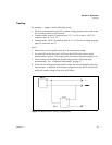
1. Select remote voltage programming by moving the rear panel switch S1-5
(remote voltage program select) to the ON (closed) position.
Or, connect J5 pin 7 (remote voltage program select) to J5 pin 6 (auxiliary
ground). As these two control functions are wired in parallel, they function as a
logic OR.
2. Set rear panel switch S1-4 (resistive voltage program select) to the ON (closed)
position.
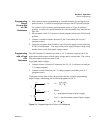
3. Connect a variable resistor between pin 17 (voltage program) and either pin 4 or
pin 5 (program return).
4. Adjust the resistance from 0-10kΩ to vary the power supply output from 0-100%
of rated output voltage. You may set the power supply's output current limit
using another source or the front panel current limit control.
Programming
Output
Current with
a 0-10 Vdc
Voltage
Source
1. Select remote current limit programming by moving the rear panel switch S1-3
(remote current program select) to the ON (closed) position.
Or, connect J5 pin 8 (remote current program select) to J5 pin 6 (auxiliary
ground). As these two control functions are wired in parallel, they function as a
logic OR.
2. Connect the voltage source between J5 pin 16 (current program, positive) and
either pin 4 or pin 5 (program return).
3. Vary the external voltage from 0-10Vdc to cause the power supply current limit
to vary from 0-100% of rated output. You may set the power supply's output
voltage using another source or the front panel voltage control.
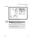
Access the zero offset adjustment and full range scale adjustment through top cover
slots as shown in Figure 2.3, pg. 17.