Section 3. Operation
Readback and Status Indicators
22 Operating Manual for APG for XT/HPD Series Power Supply
Readback and Status Indicators
Voltage and
Current
Readback
Voltage Readback
• Connect a meter between J5 connector pin 19 (voltage readback) and either pin
4 or 5 (program return).
Range: 0-10V = 0-100% full rated voltage output of power supply
Current Readback
• Connect a meter between J5 connector pin 18 (current readback) and either pin
4 or 5 (program return).
Range: 0-10V = 0-100% full rated current output of power supply
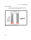
Note:The voltage and current readback signals have adjustable offset and range.
These adjustments are accessible from the top of the power supply (see Figure 2.3,
pg. 17). The adjustments are independent of other power supply calibrations or
adjustments such that APG readback can be zero and range calibrated without
affecting other power supply parameters.
Operating
Mode Status
• Connect voltmeter between J5 connector pin 9 (voltage/current limit mode
indicator) and pin 6 (auxiliary ground).
Voltage Mode: active low open collector
Current Mode: high impedance open collector
Remote
Programming
Status
Remote programming status is available via J5 connector pins 7 (remote voltage
program select) and 8 (remote current program select). Reference to J5 connector at
either pin 4 or 5 (program return).
J5-7 LOW = Remote Voltage Program, HIGH=Local Front Panel Control
J5-8 LOW = Remote Current Program, HIGH=Local Front Panel Control
Output Fail
Flag
The Output Fail Flag (J5 connector pin 21) signal is HIGH (open collector) when any
one of the following conditions is true:
• AC input to the power supply is below operating limits.
• Over voltage protection is activated.
• TTL shutdown is active.
• Sense line protect circuit is active (excessive load line drop or load line(s) not
connected or fuse(s) in power supply blown).


