


10
975-0123-01-01 Rev A
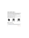
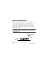
Cable Installation (Step 2)
Connect the display to the controller using the serial communications
cable provided. The cable is a six-conductor telephone cable with
modular-type connectors (RJ-15). Although any telephone-type cable
will work, the cables provided with the displays use stranded and
tin-plated wire for better performance and longer life.
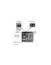
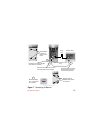
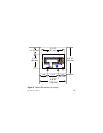
The following instructions are illustrated in Figure 6.
To connect the Faceplate to the C-Series controller:
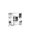
1. Remove the front cover of the C-Series controller by removing the
four screws on the front cover of the unit.
2. Remove the LED on the circuit board of the C-Series controller
next to the RJ-15 Port just above the
BATTERY POSITIVE connector.
If the LED must be replaced in the future, it will operate in either
orientation, except if replaced incorrectly, the color of the status
LED will be reversed.
3. Insert the serial communications cable from the faceplate into the
RJ-15 Port.
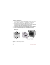
4. Align the faceplate on the front of the C-Series controller so that the
holes for the faceplate match.
5. Secure the faceplate in place using the four screws removed in
Step 1.