


Installation
46 975-0004-01-02 Rev D
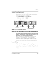
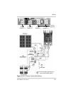
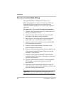
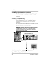
Diversion Control Mode Wiring
The procedure below is illustrated in Figure 2-24.
When using the C-Series unit as a Diversion or DC Load
Controller, the DC load needs to be connected to the
controller terminals marked as
PV +/LOAD+ and COMMON
NEGATIVE.
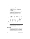
To connect the C-Series as a diversion load controller:
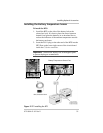
1. Connect your DC current source (PV, wind, hydro, etc.)
directly to the RE disconnect.
2. Connect another cable from the other side of the RE
disconnect to the battery positive terminal.
3. Run a negative wire from the DC current source (PV,
wind, hydro, etc.) to the battery negative terminal.
4. Connect a cable from controller terminal marked BAT
POS to the battery disconnect.
5. Connect a cable from the battery disconnect to the
positive terminal of the battery.
6. Connect a cable from the negative battery terminal to one
of the terminals marked C
OMMON NEGATIVES on the
controller’s circuit board.
7. Connect a cable from the controller’s other terminal
marked C
OMMON NEGATIVES to the negative terminal of
your DC diversion load.
8. Connect a cable from the controller’s terminal marked
PV+/LOAD+ to the positive terminal of your DC
diversion load.
9. Tighten per torque requirements outlined on page 39.
Allow a little slack on the cables within the controller and
secure the wiring with strain reliefs.
Important:
Do not use light bulbs for diversion loads. Use
only resistive loads such as air- or water-cooled heating elements