


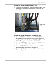
Cable Installation
152602 2–13
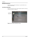
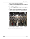
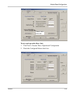
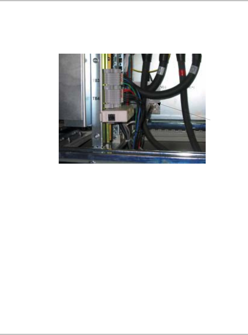
To install the MS100E Interface Assembly Cable:
1. Connect the MS100E Interface Assembly cable J20 to the GT100E
Option Panel P20, located at the bottom/rear of the cabinet, see
Figure 2-10.
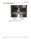
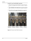
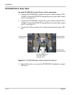
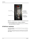
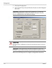
To install the MS100E Control Power and Interface Cable:
1. Route the MS100E Power Cable assembly P/N 1-152492-01 and
MS100E Interface cable assembly P/N 1-152493-01 through the
Input/Output Access Base Panel on the GT100E unit. Reference the
GT100E Planning and Installation Manual P/N 152364
2. Connect the MS100E Power cable assembly to the MS100E Interface
Assembly connector P22, see Figure 2-11.
3. Connect the MS100E Interface cable assembly to the MS100E
Interface Assembly connector P21, see Figure 2-11.
4. Connect both of the cable ground wires to the ground terminal using a
M5 nut, see Figure 2-11.
Figure 2-10
GT100E MS Interface Assembly Cable Connection
Option Panel
P20