


Remote Operation
4–4 TM-XDOP-01XN
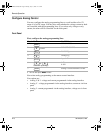
Remote Analog Operation
Analog Connections
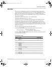
The analog interface has 2 ports: the user lines and the analog programming lines.
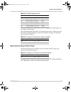
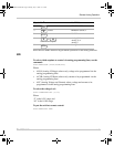
The tables below show the function and power flow for each pin on these ports.
The user lines are optically isolated. The output lines are open collector
configuration. The input lines are capable of sinking 10mA (with recommended
5V at input) up to a maximum 90mA.
The analog program and monitor lines are fully isolated from the supply output,
but not each other. Isolation to chassis is limited to 58 V.
Use precision variable low noise voltage sources for the program lines, and be
sure that the program source ground potential is the same as on the analog
readback circuitry.
The external analog monitoring circuitry must be high impedance because the
onboard V and I readback sources have approximately 300 ohms output
impedance.
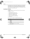
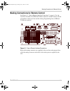
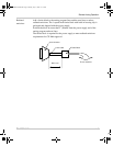
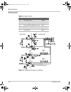
Connect your program and readback lines to the removable wire clamp connectors
marked “user lines” and “program lines” in Figure 4-1. Strip 0.2” (5mm) of
insulation from the wires and clamp securely at the appropriate pin. See Table 4-1,
Figure 4-1 and Table 4-2 for the location and function of each connector.
Use shielded twisted pairs of 22–24AWG for signal connections.
CAUTION
To avoid damage to the power supply, do not apply signals to Analog programming lines
in excess of 58 V wrt chassis, or 12 V wrt Analog programming ground.
TM-XDOP-01XN.book Page 4 Monday, July 17, 2006 11:19 AM