


26
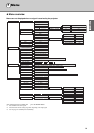
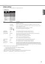
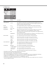
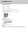
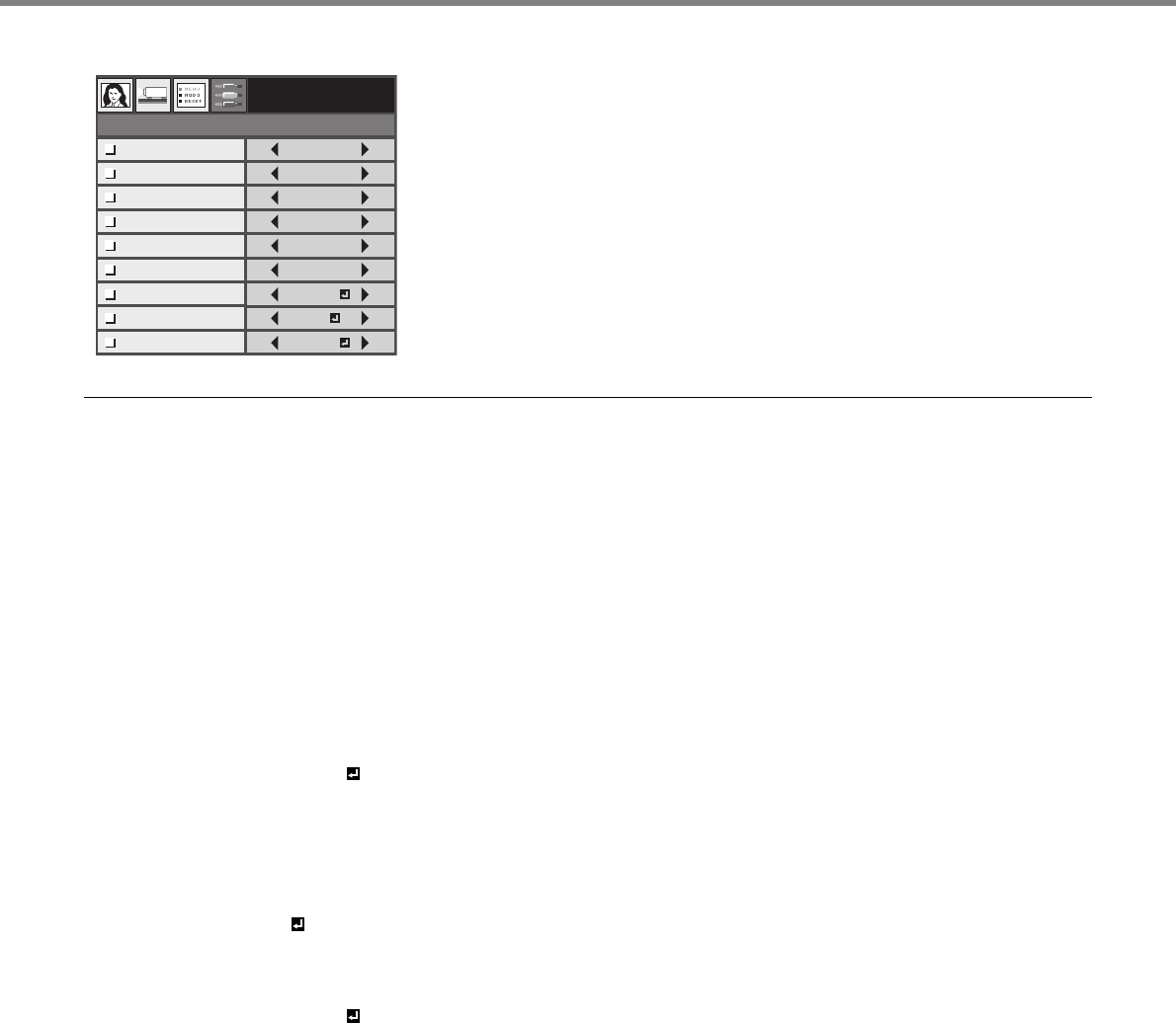
4. SIGNAL menu
* The default value and the setting range differ depending on the input signals.
• Horizontal strips may appear on the enlarged projected image.
• When changing a horizontal or vertical position to a large extent, noise may appear.
• When you select COMPONENT as an input source, the setting of D-SUB INPUT will be changed to COMPONENT automatically.
• OVER SCAN and BLACK MASK are not available when the aspect ratio is set to SMART ZOOM (see page 18).
• OVER SCAN is not available when the aspect ratio is set to THROUGH (see page 18).
• If you increase the OVER SCAN setting when the projector is receiving the video signals, noise may appear on the screen. In such case,
decrease the OVER SCAN setting.
SIGNAL
0 - 999
0 - 999
0 - 31
0 - 999
100 - 90%
AUTO
ON
HORIZ. POSITION
VERT. POSITON
PHASE
TRACKING
OVER SCAN
D-SUB INPUT
SYNC NOISE
MASK
EXECUTE
A/D SETTING
TV60
EXECUTE
BLACK MASK
ITEM SETTING FUNCTION
HORIZ. POSITION
0 – 999*
Use to adjust the horizontal position of the projected image.
VERT. POSITION
0 – 999*
Use to adjust the vertical position of the projected image. The adjustable range varies
depending on the type of the input signal. In some cases, the image may stay in the same
position even when the setting value is changed.
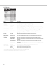
PHASE
0 – 31*
Use to eliminate flickering or blur, if it appears while viewing the projected image.
TRACKING
0 – 9999*
Use to eliminate vertical wide stripes, if it appears, while viewing the projected image.
OVER SCAN
100% – 90%*
Use to adjust the over scan ratio for the video signals.
D-SUB INPUT AUTO When the projector detects the three-wire system (YC
B
C
R
/ YP
B
P
R
) or five-wire system
(RGBHV), it automatically selects either COMPONENT or RGB accordingly.
RGB Select this option when connecting the projector to high definition video equipment having
R, G, and B output terminals.
COMPONENT Select this option when connecting the projector to a DVD player or other equipments having
Y, C
B
, and C
R
(or Y, P
B
, and P
R
) component video output terminals.
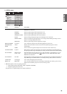
BLACK MASK
EXECUTE
Use to adjust the image when the noise appears on the projected image.
TOP Adjust the image when the noise appears on the top part of the image.
BOTTOM Adjust the image when the noise appears on the bottom part of the image.
LEFT Adjust the image when the noise appears on the left part of the image.
RIGHT Adjust the image when the noise appears on the rigtht part of the image.
SYNC NOISE MASK
ON , OFF
Use to adjust the image when flagging occurs near the top of the screen.
BEGIN Use to adjust the start of the sync noise mask position.
END Use to adjust the end of the sync noise mask position.
A/D SETTING
EXECUTE
Use to adjust the Analog Digital conversion parameters.
CLAMP POSITION Use to correct solid white or solid black in the projected image.
CLAMP WIDTH Use to correct solid black in the projected image.
VERT. SYNC Use to adjust the image when its motion does not run smoothly.
LPF Use to reduce the streak noise appeared on the image. (see page 29).