YMF724F
September 21, 1998
-14-
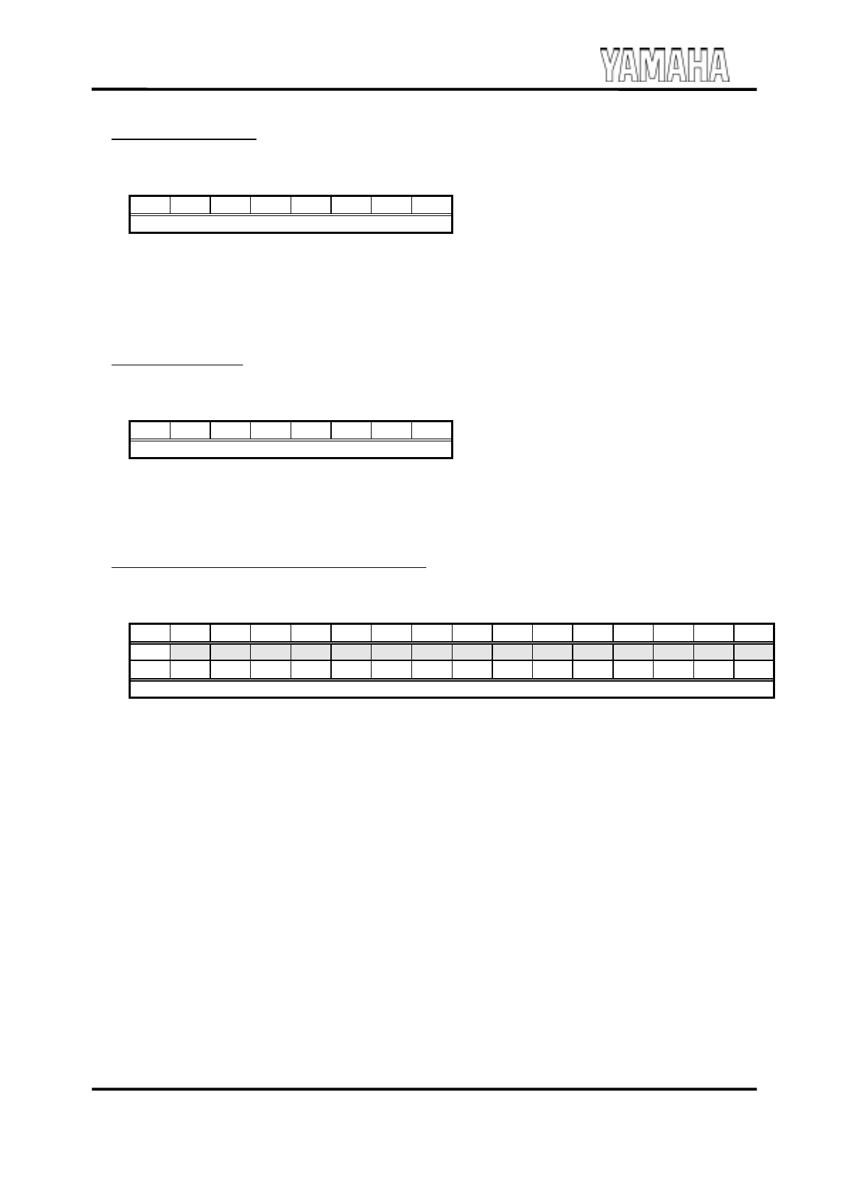
0Dh: Latency Timer
Read / Write
Default: 00h
Access Bus Width: 8, 16, 32-bit
b7 b6 b5 b4 b3 b2 b1 b0
Latency Timer
b[7:0] ..........Latency Timer
When DS-1 becomes a Bus Master device, this register indicates the initial value of the Master Latency
Timer.
0Eh: Header Type
Read Only
Default: 00h
Access Bus Width: 8, 16, 32-bit
b7 b6 b5 b4 b3 b2 b1 b0
Header Type
b[7:0] ..........Header Type
This register indicates the device type of DS-1. This is hardwired to 00h.
10 - 13h: PCI Audio Memory Base Address
Read / Write
Default: 00000000h
Access Bus Width: 8, 16, 32-bit
b15 b14 b13 b12 b11 b10 b9 b8 b7 b6 b5 b4 b3 b2 b1 b0
MBA
- - - - - - - - - - - - - - -
b31 b30 b29 b28 b27 b26 b25 b24 b23 b22 b21 b20 b19 b18 b17 b16
MBA (higher)
b[31:14] ......MBA: Memory Base Address
This register indicates the physical Memory Base address of the PCI Audio registers in DS-1. The base
address can be located anywhere in the 32-bit address space. Data in the DS-1 register is not
prefetchable.
DS-1 needs 32768-bytes of memory address space.


