


Chapter 2 Hardware Description and Connection
ES1100 Series User’s Guide
15
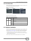
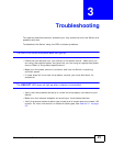
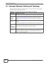
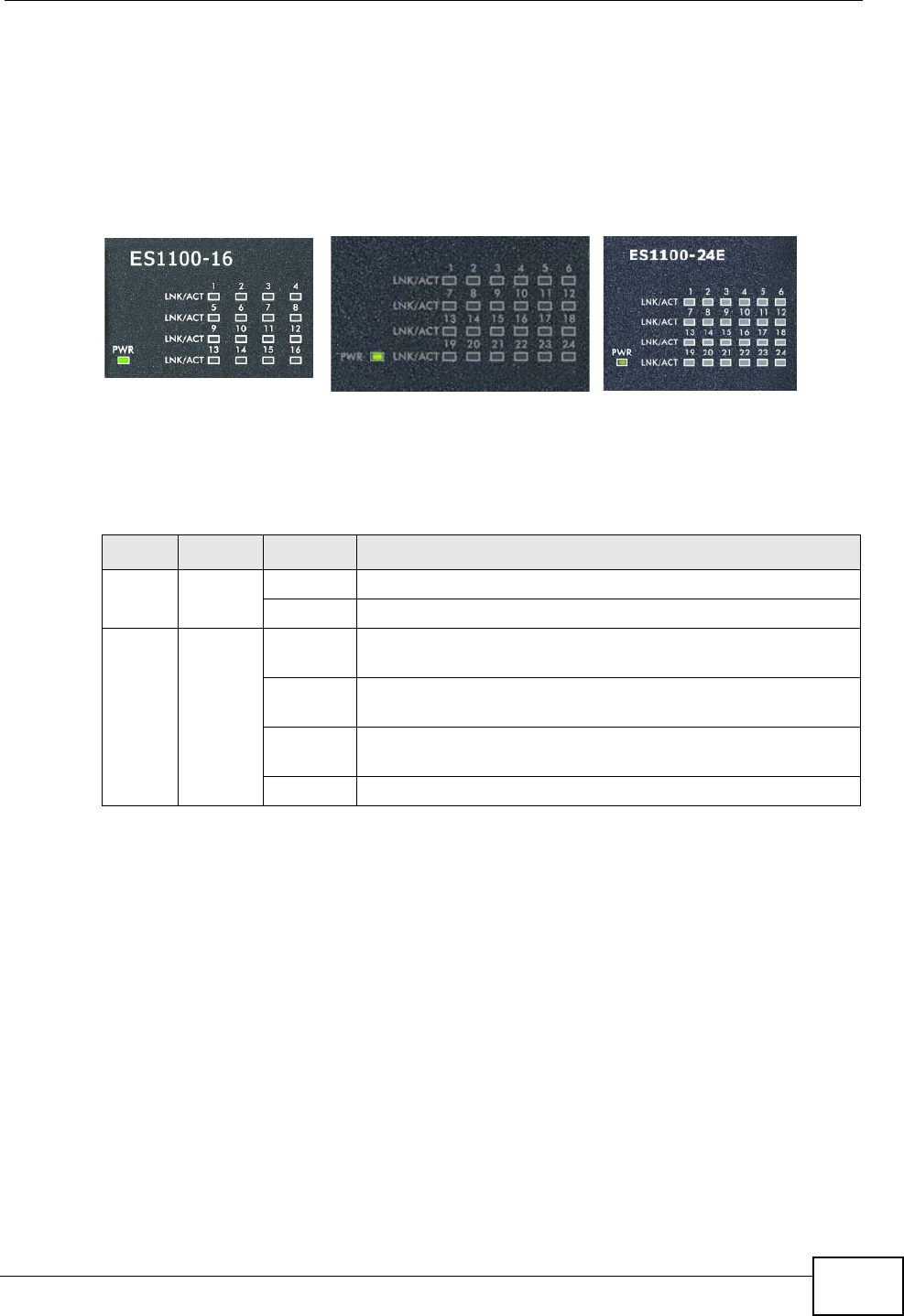
2.2.3 Front Panel LEDs
The LED Indicators give real-time information about the status of the Switch. The
following table provides descriptions of the LEDs.
Figure 5 Front Panel LEDs
The following table describes the LEDs.
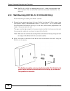
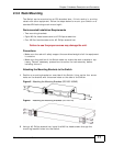
2.3 Hardware Installation
For ES1100-16/24E, you can place the Switch directly on top of your desk or have
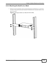
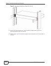
it rack-mounted. For ES1100-24, the size is suitable for rack-mounting and you
can refer to Section 2.3.2 on page 17 for instruction. Take note of the following:
• The Switch should have a minimum 25 mm space around it for ventilation.
• The Switch should be placed in a desk that has a level surface and that is able to
support the weight of the Switch.
To start using it, simply connect the power cables and turn on the Switch.
Table 2 The Front Panel LED Descriptions
LED COLOR STATUS DESCRIPTION
PWR Green On The Switch is on and receiving power.
Off The Switch is not receiving power.
LINK/
ACT
Green On The port is connected to an Ethernet network at 10M or
100M speed.
Blinking
(Normal)
The port is receiving or transmitting data.
Blinking
(Slow)
The Ethernet network link is down due to loop detection.
Off The port is not connected to an Ethernet network.
ES1100-16
ES1100-24
ES1100-24E