


Dimension GS-1008/GS-1016 Gigabit Ethernet Switch
List of Figures/Tables xi
List of Figures
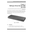
Figure 1-1 GS-1008 ...................................................................................................... 1-1
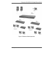
Figure 1-2 Backbone Switch Application .....................................................................1-3
Figure 2-1 Attaching Rubber Feet.................................................................................2-2
Figure 2-2 Attaching Mounting Brackets and Screws .................................................. 2-3
Figure 2-3 Mounting the Switch to an EIA Standard 19-inch Rack ............................. 2-3
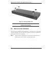
Figure 2-4 GS-1008 Rear Panel.................................................................................... 2-4
Figure 2-5 GS-1016 Rear Panel.................................................................................... 2-4
Figure 2-6 GS-1008 Front Panel...................................................................................2-4
Figure 2-7 GS-1016 Front Panel...................................................................................2-5
Figure 2-8 GS-1008 LEDs............................................................................................ 2-6
Figure 2-9 GS-1016 LEDs............................................................................................ 2-6
List of Tables
Table 2-1 Network Cable Types ...................................................................................2-5
Table 2-2 Front Panel LED Descriptions.....................................................................2-7
Table 3-1 Troubleshooting PWR LED .........................................................................3-1
Table 3-2 Troubleshooting LK/ACT LED.................................................................... 3-1
Table 3-3 Troubleshooting 100, 1000 LEDs.................................................................3-2
Table 3-4 Troubleshooting FD LED.............................................................................3-2
Table 3-5 Troubleshooting Improper Network Cabling and Topology ........................3-3