


Chapter 3 Hardware Overview
XGS4700-48F User’s Guide
52
3.4 LEDs
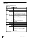
The following table describes the LEDs.
Table 3 LEDs
LED
COLO
R
STATUS DESCRIPTION
Displays
Stack ID
number
The LED is showing the Stack ID number of the Switch.
PWR1
(Power 1)
Green On The system is receiving power from the power module in
the first power slot.
Off The system is not receiving power from the power
module in the first power slot.
Amber On The power module in the first power slot fails to supply
power or its fan is not functioning at a proper speed.
PWR2
(Power 2)
Green On The system is receiving power from the power module in
the second power slot.
Off The system is not receiving power from the power
module in the second power slot.
Amber On The power module in the second power slot fails to
supply power or its fan is not functioning at a proper
speed.
SYS
(System)
Green Blinking The system is rebooting and performing self-diagnostic
tests.
On The system is on and functioning properly.
Off The power is off or the system is not ready or
malfunctioning.
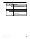
ALM
(Alarm)
Red On There is a hardware failure, such as high device
temperature, wrong voltage and abnormal fan speed.
Off The system is functioning normally.
MGMT
(Manage
ment)
Green Blinking The system is transmitting or receiving to/from an
Ethernet device at 10 Mbps through the MGMT port.
On The MGMT port is connected at 10 Mbps.
Off The MGMT port is not connected at 10 Mbps or to an
Ethernet device.
Amber Blinking The system is transmitting or receiving to/from an
Ethernet device at 100 Mbps through the MGMT port.
On The MGMT port is connected at 100 Mbps.
Off The MGMT port is not connected at 100 Mbps or to an
Ethernet device.
Mini-GBIC (SFP) Slots