1. Install hydraulic unit into receiver and secure with provided 7.5mm X 22mm bolt.
2. Install lift foot pedal into sleeve.
3. Install handle into frame and secure using the provided pins(2).
4. Ensure assembly rolls freely, lifts, locks, and lowers easily. Get to know how the release pedal, lift pedal,
and the height locking and unlocking mechanism work prior to loading the Lift.
Do not use if cracked, broken, bent or otherwise damaged parts are noted or if the lift is suspected to have been
subjected to a shock load. A shock load is caused by rapidly opening and closing the release valve while the lift
is loaded. Such operation may result in a hydraulic overload which may disable the hydraulic unit. Owner and
operators of this device shall be aware that no serviceable or replaceable parts are available for this device other
than those parts listed on page 4. Any lift that appears to be damaged in any way, is worn or operates abnor-
mally shall be removed from service immediately until such time as repairs can be made.Do not attempt to weld,
rivet or otherwise repair this device. DO NOT modify or alter this device. It is recommended that an annual
inspection be done to this device by qualified persons and that missing or damaged labels, warning/safety
decals be replaced with ones that are factory authorized.
1. Position lift under appropriate lift point centering load on lift saddle.
2. Locate and pump the lift foot pedal until the lift saddle comes into contact with an appropriate
lift point.
3. Only after centering the load, slowly and carefully raise the lift arm by pumping the lift foot pedal.
4. Lock both swivel casters by pressing down on the caster lever marked ‘lock’.
5. Continue pumping until the load has reached desired height. Secure the load using appropriate tie down
means. Four tie down loops have been provided on the frame of the lift, 2 fore and 2 aft. Make sure that the
height locking mechansim is fully engaged before working on or around the loaded Lift.
6. To lower lift, disengage height locking lever and depress release pedal.
ASSEMBLY
!
!
OPERATING INSTRUCTIONS
!
!
INSPECT BEFORE EACH USE
!
!
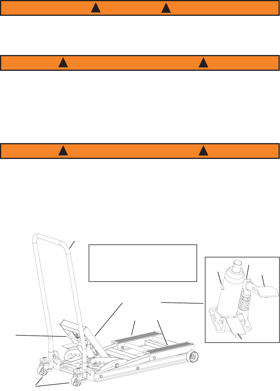
KNOW YOUR LIFT
Release Pedal
Hydraulic Unit
Lift Pedal
Sleeve
Handle
Lift Saddle
Height
Locking/Unlocking
Lever
Oil Filler
Plug
Casters
3
Press Height Locking Lever Forward
Against Hydraulic Unit to Engage
Locking Mechanism.
Pull Lever Back Over Lift Pedal
To Disengage Locking Mechanism


