3-26 Cisco IGX 8400 Series Installation and Configuration
Making Serial Data Connections
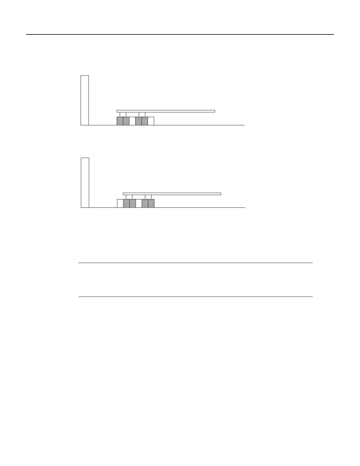
Figure 3-12 Changing the Mode on an SDI Card
HDM and LDM Redundancy
Optional redundancy for HDM and LDM cards can be provided with a second front and back card
set and a Y-cable connection on each port to the customer data equipment.
Note A jumper board comes with an impedance of either 100 ohms or 200 ohms. For higher port
speeds, the impedance is important if you have specified Y-cable redundancy. With Y-cable
redundancy on a higher-speed connection, use the 200-ohm jumper board. With no Y-cable
redundancy or when the port speed is relatively low, the 100-ohm jumper board is adequate.
Configuring the Mode of an LDI Port
Each porton anLDI carduses anadapter cable.For alist ofLDI adaptercables, referto Appendix C,
“Cabling Summary.” Each cable does the following:
• Determines whether the port operates in DCE mode or DTE mode
• Connects the port’s 15-pin connector to a 25-pin D connector
• Converts to either a male or female pinout
See Figure 3-13 for an example. In Figure 3-13, the adapter cable makes the port a DCE port.
Circuits on the card test certain pins on the cable then configure the port as DTE or DCE.
Faceplate
DCE/DTE
jumper board
DCE position
SDI
123456
Faceplate
DCE/DTE
jumper board
DTE position
SDI
123456
H8370


