M:\Product Information\366-348\Instructions\366-348 MGB Fuel Injection Installation Instructions_Grant_2.doc
366-348 Inst Fi
110
110.1
110.2
110.3
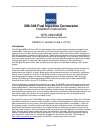
175. Find the three 2 3/8” long Allen head bolts for
the air intake housing and the packet of blue Loctite,
all of which are supplied in the kit.
176. Test fit all the mounting bolts in the throttle body
before opening the Loctite. Start with the lower rear
bolt (110.1). You may find it necessary to insert at
least this bolt into the air intake housing before you
slide the air filter/housing into place. Get this bolt
started, then start the other two (110.2, 100.3). If you
have any trouble getting the bolt to start, DO NOT
FORCE THEM! You are threading into aluminum,
and you can ruin the throttle body by being
impatient. If necessary, remove the housing and test
fit the bolts in the holes one at a time.
366-348 Inst Fig 111
177. Once you have verified that all will start, remove
them and put a little Loctite on the threads of each
bolt
178. Start with the lower rear bolt (110.1). Get this
bolt started, then start the other two (110.2, 100.3)
Tighten the screws with a 5mm Allen wrench. (Fig
111) DO NOT over tighten or the intake housing will
crack.
366-348 Inst Fig 112
112.3
112.2
112.4
112.1
366-348 Inst Fig 115
115.1
179. Move to the front of the engine.
180. We left one end of the 5/8” hose attached to the
air intake housing loose. Route the loose end of the
hose (112.2) behind the gulp valve-to-air pump hose
(112.3).
181. Slide on a medium-sized hose clamp (112.4),
and slip the hose over the crankcase ventilation tube
(112.1).
182. Tighten the hose clamp (112.4).
183. Tighten the hose clamp (115.1) securing the air
filter to the air intake assembly. Male sure the nut on
the clamp winds up in a position that can be reached
with the air intake assembly in place.
This complete part 15 of the installation
Page 28 of 52