M:\Product Information\366-348\Instructions\366-348 MGB Fuel Injection Installation Instructions_Grant_2.doc
Cut or fold paper along dotted line, then
align this edge of the paper against the
right hand side kick panel
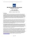
ECU Mounting Template
The dimensions are given so that you can
verify that printing or copying the template has
not affected the accuracy of the hole locations.
Lay the ECU on top of the template and make
sure the hole locations in the mounting flange
have not been changed.
Cut or fold the paper along the dotted line, then align this
edge of the paper with the bend in the sheet metal under
the dash. This edge is closest to the seat. The end of the
ECU with the large rectangular connectors faces seat.
Towards the firewall
Mark and
center-punch
these 3 holes
2 ” to the dotted line
Hole #1
3 9/16 “ center to center
2 ¼ ” to the dotted line
6 9/16 ” center to center
Page 52 of 52