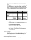
• Three 10/100/1000BaseT GigabitEthernet LAN ports with two LEDs
on each port, instead of the two 10/100BaseT FastEthernet LAN
ports
• Mini-Gigabit Interface Converter (MGBIC) fiberoptic port plus two
LEDs
• Two NCC slots with two NIM slots on each card
• No power switch
• No default configuration button
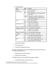
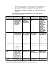
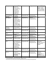
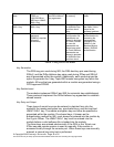
All of these physical ports are separated into logical interfaces defined by
FIPS 140-2, as described in Table 3:
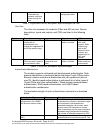
Module Physical Ports FIPS 140-2 Logical Interface
Network ports Data input interface
Network ports Data output interface
Network ports, console port,
power switch (XSR-18xx only),
default button (XSR-18xx only)
Control input interface
Network ports, console port,
LEDs
Status output interface
Power connector(s) Power interface
Table 3 – FIPS 140-2 Logical Interfaces
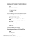
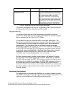
Data input and output, control input, and status output are defined as
follows:
• Data input and output are the packets that use the firewall, VPN,
and routing functionalities of the modules.
• Control input consists of manual control inputs for power and reset
through the power and reset switch. It also consists of all of the
data that is entered into the module while using the management
interfaces.
• Status output consists of the status indicators displayed through the
LEDs and the status data that is output from the modules while
using the management interfaces.
The modules distinguish between different forms of data, control, and
status traffic over the network ports by analyzing the packets header
information and contents.
© Copyright 2003 Enterasys Networks Page 10 of 25
This document may be freely reproduced and distributed whole and intact including this Copyright Notice.