Quick Start — MVP 104GX
Installation
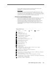
Step 1
Turn off power to the MVP 104GX and all other
devices that will be connected.
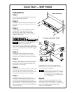
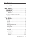
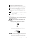
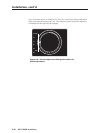
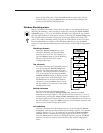
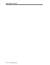
Step 2
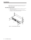
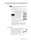
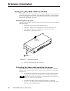
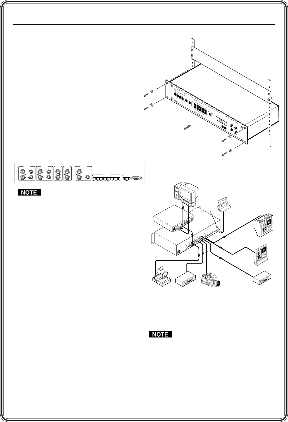
If the MVP 104GX is to be rack mounted, insert
the mounting screws and washers, as shown on
the right.
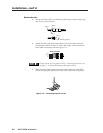
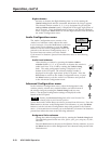
Step 3
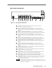
Using Inputs 1, 2, 3, and 4, attach up to four
composite/S-video input devices to the
MVP 104GX. Inputs 1 and 2 can be either
composite video or S-video, inputs 3 and 4 are
composite video only.
Any inputs must be either all NTSC or
all PAL, they cannot be both.
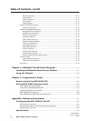
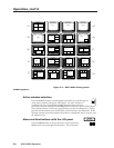
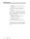
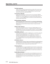
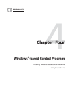
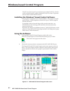
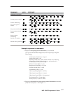
The buffered loopout connectors for all inputs
can be used to output the identical signal to other
devices. See the application connection diagram
on the right.
Step 4
Connect up to three output devices to the
MVP 104GX using composite video output A,
composite video output B, and S-video output C.
Step 5
For stereo audio input, connect up to four audio
sources to audio inputs 1, 2, 3, and 4. See the
Audio input and output section in chapter 2 for
illustrations and warnings.
Step 6
For stereo audio output, connect an audio output
device to the 3.5 mm stereo audio output
connector. See the Audio input and output section
in chapter 2 for illustrations and warnings.
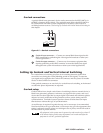
Step 7
If the MVP 104GX is to be connected to a
computer or host controller for remote control,
connect the host’s RS-232/RS-422 cable to the
9-pin female RS-232/RS-422 remote connector of
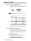
the MVP 104GX. For an RS-232/RS-422 pinout
table, see the Remote Control Port (RS-232/RS-422)
section in chapter 5.
REMOTE
RS-232/RS-422
INPUT 1
IN
OUT
INPUT 2
IN
OUT
OUTPUT
A
BC
1LR
INPUTS OUTPUT
INPUT 3
IN
OUT
INPUT 4
IN
OUT
2LR3LR4LR 1LR
If a genlock device is to be connected to the
MVP 104GX, see Setting Up Genlock and Vertical
Interval Switching in chapter 2.
The MVP 104GX comes from the factory
already configured for RS-232. To set the
MVP 104GX for RS-422 operation, refer
to “Configuring the MVP 104GX for RS-
422” in the appendix.
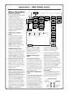
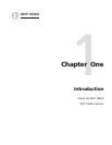
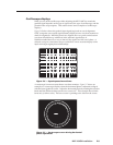
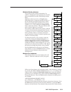
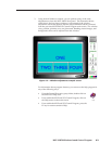
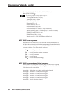
Step 8
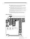
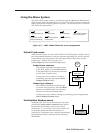
Power up the input and output devices, then
connect power to the MVP 104GX. A summary
of the menu system is described on the following
page. See the appropriate chapters in this
manual for further details.
IN
PU
T
S
P
R
E
S
E
T
S
A
D
JU
S
T
M
E
N
T
S
1
2
3
4
4
3
2
1
F
R
E
E
Z
E
A
U
D
IO
4
3
2
1
A
C
T
IVE
N
E
X
T
M
E
N
U
A
D
JU
S
T
S
T
O
R
E
F
A
C
TO
R
Y
P
A
T
T
E
R
N
S
M
V
P 10
4G
X
M
U
L
T
I
V
I
D
E
O
P
R
O
C
E
S
S
O
R
Rack mounting
R
E
M
O
T
E
R
S
-
2
3
2
1
0
0
-
2
4
0
V
5
0
/
6
0
H
z
0
.
5
A
I
N
P
U
T
1
IN
OUT
I
N
P
U
T
2
IN
OUT
O
U
T
P
U
T
A
B
C
1L
R
I
N
P
U
T
S
O
U
T
P
U
T
I
N
P
U
T
3
IN
OUT
I
N
P
U
T
4
IN
OUT
2
L
R
3
L
R
4
L
R
1
L
R
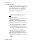
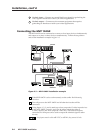
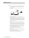
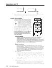
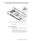
RS-232 Control
External
Genlock
Timing
MVP 104GX
Document Camera
VCR
VCR
Plasma Display
Videoconferencing System
Video Camera
5
0
/
6
0
H
z
1
0
0
-
2
4
0
V
0
.
3
A
S
-
V
I
D
E
O
R
-
Y
/
B
-
Y
/
Y
R
G
B
R
/
R
-
Y
H
V
S
G
/
YB
/
B
-
Y
R
S
-
2
3
2
O
U
T
I
N
G
E
N
L
O
C
K
S
-
V
I
D
E
O
PAL OUT
75 OHM
V
I
D
E
O
M
A
C
V
G
A
I
N
P
U
T
S
O
U
T
P
U
T
S
PC Computer
A
N
A
H
E
I
M
D
i
s
n
e
y
l
a
n
d
B
A
L
L
R
D
.
L
I
N
C
O
L
N
A
V
.
STATE COLLEGE BLVD.
A
N
A
H
E
I
M
B
L
V
D
.
LEWIS ST.
A
na
h
e
i
m
S
t
a
di
u
m
K
A
T
E
L
L
A
A
V
.
CERR
IT
O
S
A
V.
DOUGLAS RD.
E
A
S
T
S
T
.
HASTER ST.
WEST ST.
E
x
t
r
o
n
5
5
7
A
N
A
H
E
I
M
D
i
s
n
e
y
l
a
n
d
B
A
L
L
R
D
.
L
IN
C
O
L
N
A
V
.
STATE COLLEGE BLVD.
A
N
A
H
E
I
M
B
L
V
D
.
LEWIS ST.
A
n
a
h
e
i
m
S
t
a
d
i
u
m
K
A
T
E
L
L
A
A
V
.
C
E
R
R
I
T
O
S
A
V
.
DOUGLAS RD.
E
A
S
T
S
T
.
HASTER ST.
WEST ST.
E
x
t
r
o
n
5
5
7
A
N
A
H
E
I
M
D
i
sn
e
y
l
a
n
d
B
A
L
L
R
D
.
L
I
N
C
O
L
N
A
V
.
S
T
A
T
E
C
O
L
L
E
G
E
B
L
V
D
.
A
N
A
H
E
I
M
B
L
V
D
.
L
E
W
I
S
S
T
.
A
nah
e
im
S
t
a
d
iu
m
K
A
T
E
L
L
A
A
V
.
C
E
R
R
I
T
O
S
A
V
.
D
O
U
G
L
A
S
R
D
.
E
A
S
T
S
T
.
H
A
S
T
E
R
S
T
.
W
E
S
T
S
T
.
E
x
t
r
o
n
5
5
7
Extron
VSC 150
Scan
Converter
Connecting the MVP 104GX