P/2 DA2 WM/EC/D/AAP Series • Controls and Installation
P/2 DA2 WM/EC/D/AAP Series • Controls and Installation
2-6
Controls and Installation, cont’d
Installing the P/2 DA2 WM F/EC F
Easy setup procedure
The wall-mounted P/2 DA2 WM F kit consists of the faceplate/
distribution amplifier assembly and a mounting bracket that
mounts in a wall opening and to which the faceplate assembly is
attached. The P/2 DA2 WM EC F kit consists of the faceplate/
distribution amplifier assembly that mounts in the Euro
Channel raceway.
1
For wall mounting only: Using the mounting template
provided in the appendix as a guide, carefully cut a
mounting hole through the wall where the mounting
bracket is to be installed.
2
For wall mounting only: Install the mud ring mounting
bracket using the supplied screws and mounting clips.
Refer to the section “Installing a mud ring bracket” for
further details.
3
Before connecting any cables, power off all equipment. If
the optional architectural adapter plate (AAP) is being
installed, please refer to “Installing architectural adapter
plates” in this chapter.
4
The rear connectors are the same for both WM F and WM
F EC models. Connect the VGA output cable to the 15-pin
HD female output connector. To prevent installation
debris or objects from entering the opening in the sheet
metal just above this VGA connector, use masking tape to
temporarily cover this opening. Remove this tape after
installation is completed. Next, if there is audio output,
connect the audio output cable to the captive screw
connector. Finally, connect the power cable to the power
input connector. Refer to the “Cabling” and “Connecting
audio” sections of this chapter.
5
Before attaching the faceplate assembly to the wall
mounting bracket/Euro Channel, attach the computer
video cable to the 15-pin HD female input connector on
the faceplate. Next, a local monitor may be connected to
the 15-pin HD female buffered local monitor output
connector on the faceplate. Finally, for audio input,
connect the audio cable to the faceplate’s 3.5 mm audio
input jack. Refer to the “Cabling” and “Connecting audio”
sections of this chapter. For Euro Channel applications,
refer to the “Euro Channel installation” section.
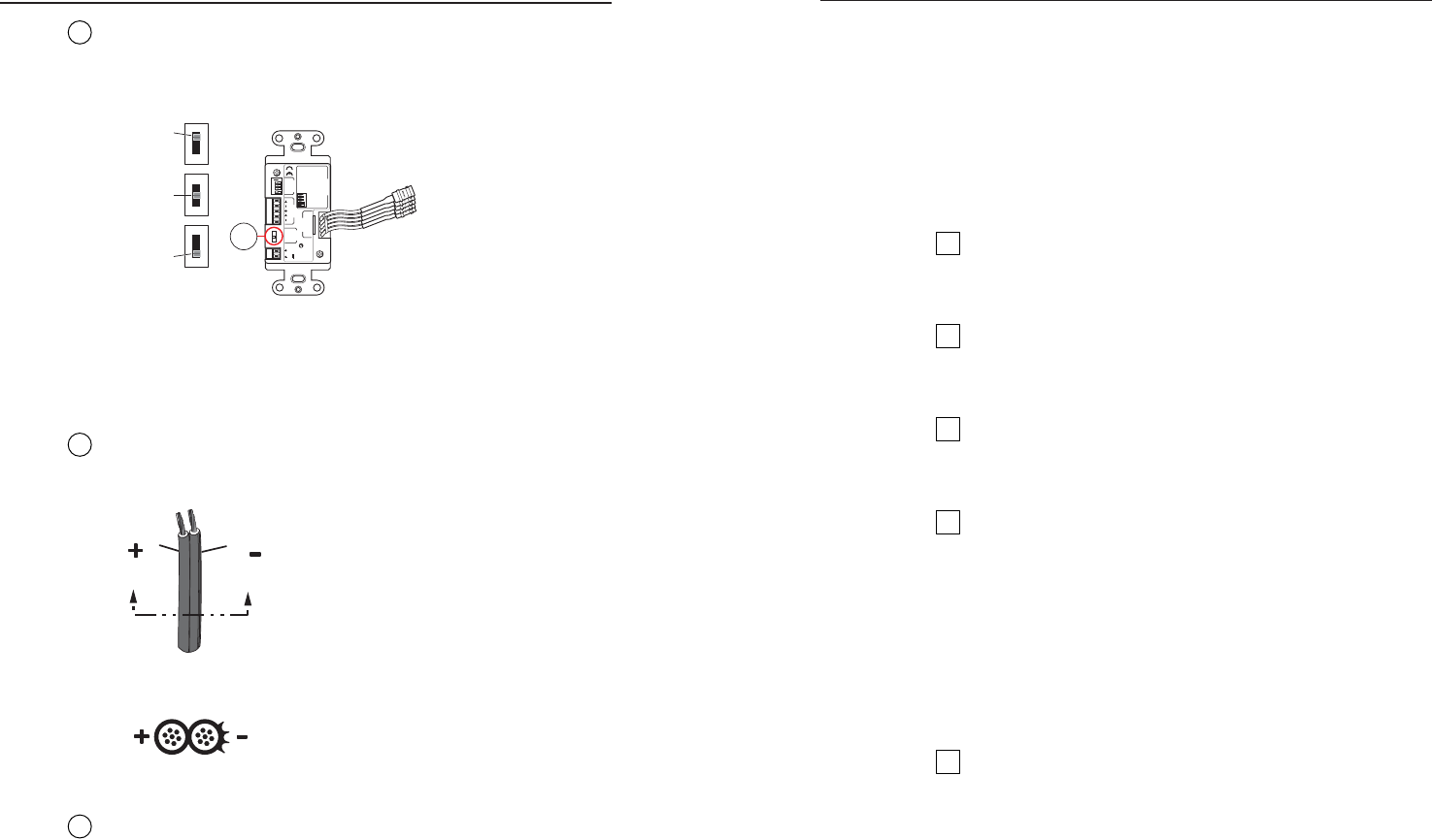
3
Gain switch — To compensate for cable resistance and
capacitance, use a small screwdriver to slide this switch to select
the level of video gain that yields the sharpest, smear-free
picture.
ON
1 2 3 4
3
12 V
0.2 A MAX
POWER
AUDIO
OUTPUT
LR
CONFIG
VIDEO
OUTPUT
P/2 DA2 D
ON
1 2 3 4
1 2 3 4
33-1663-01 A 05 08
CONFIG Switches
SW 1= Local Monitor
ON= Present, OFF= Not Present
SW 2= Audio Ouput Config
ON= Stereo, OFF= Dual MONO
SW 3= SYNC Input Impedance
ON= 510 Ohm,
OFF= 10 kOhm
SW 4= Spare
Extron Electronics
Anaheim, CA
VIDEO
GAIN
NORM
MED
HIGH
N15779
High –
Max. peaking
& gain
Medium –
Mid-level
peaking
and gain
Normal –
Unity gain
P/2 DA2 D
(viewed
from rear)
N Adjust the gain before installing the P/2 DA2 D
into a wall, as the gain switch will be inaccessible after
installation.
4
Power input — Connect the included 12 VDC external power
supply into the 2-pole, 3.5 mm captive screw connector. Be
careful to observe the correct polarity.
Power Supply
Output Cord
SECTION A–A
Ridges
Smooth
AA
5
Video output — BNC connectors for RGBHV output.
2-7


