P/2 DA2 WM/EC/D/AAP Series • Controls and Installation
P/2 DA2 WM/EC/D/AAP Series • Controls and Installation2-4 2-5
Controls and Installation, cont’d
P/2 DA2 WM F/EC F rear panel
P/2 DA2 WM F/EC F rear connectors
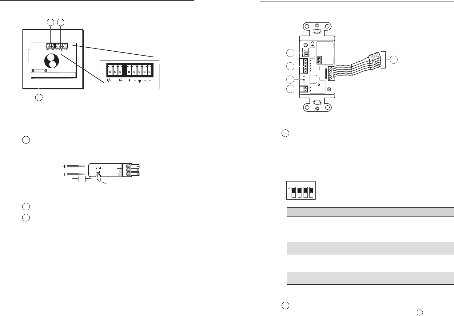
N Both WM F and WM EC F models have the same rear
panel connectors.
1
Power input — 12 - 24 VAC or DC (captive screw connector).
The center pole contains no conductor. Connect the conductors
to the outer two poles only.
2
Audio output — 3.5 mm captive screw stereo output
3
VGA output — HD 15-pin female analog video output
connector
3
NC
12-24V AC/DC
R
L
NC
12-24V AC/DC
R
L
2
1
P/2 DA2 D rear panel
ON
1 2 3 4
1
2
3
4
5
12 V
0.2 A MAX
POWER
AUDIO
OUTPUT
LR
CONFIG
VIDEO
OUTPUT
P/2 DA2 D
ON
1 2 3 4
1 2 3 4
33-1663-01 A 05 08
CONFIG Switches
SW 1= Local Monitor
ON= Present, OFF= Not Present
SW 2= Audio Ouput Config
ON= Stereo, OFF= Dual MONO
SW 3= SYNC Input Impedance
ON= 510 Ohm,
OFF= 10 kOhm
SW 4= Spare
Extron Electronics
Anaheim, CA
VIDEO
GAIN
NORM
MED
HIGH
N15779
Figure 2-5 — P/2 DA2 D rear connectors
1
Configuration DIP switches — The three DIP switches (plus
one spare) configure the P/2 DA2 D, as shown in the table
below.
N The default DIP switch positions are set to On (up).
Set these switches before installing the distribution
amplifier in a wall.
ON
1 2 3 4
Switch Function On (up) Off (down)
SW1
SW2
SW3
SW4
local monitor
(set ID bits 4
and 11)
audio output
configuration
input sync
impedance
spare
monitor present
stereo
510 ohms
n/a
monitor not present
dual mono
10k ohms
n/a
2
Audio output — 3.5 mm captive screw stereo or dual mono
output (DIP switch selectable, see switch SW 2 in
1
above).
3-Pole Captive Screw Connector
Tie Wrap
3/16”
(5 mm) Max.


