SYSTEM CONFIGURATION 21
SYSTEM CONFIGURATION
SYSTEM CONFIGURATION 21
alter a setting. The configuration settings for speaker
“size” and crossover points are set once and applied
to all inputs.
When using the full-OSD system to make the setup
adjustments, press the
OSD Button once so
that the
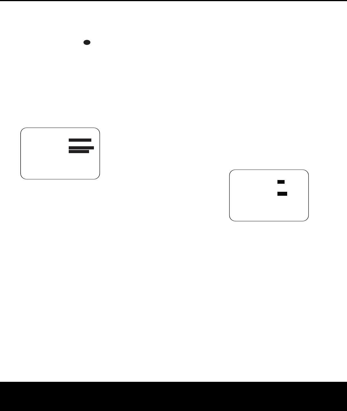
MASTER MENU (Figure 1) appears.The
➔ cursor will be next to the INPUT
SETUP
line. Press the Set Button q and the INPUT
SETUP
menu (Figure 2) will appear on the screen.
Press the
‹
/
›
Navigation Button o until the
desired input name appears in the highlighted video,
as well as being indicated in the front-panel
Input
Indica
tors
!.
When you are scrolling through the
list of available inputs, you will hear a slight click from
time to time.This is normal, as it is caused by the
relay that is used to switch between the two
Component Video inputs.
Figure 2
When one of the four Video inputs is selected as the
source, you have the option of renaming the input as it
appears in the on-screen and front panel messages.
This is helpful if you have more than one VCR, if you
wish to associate a specific product brand name with
the input,
or to simply enter any name that will help
you to remember which source is being selected.
To change the input name, press the
⁄/¤
Navigation Button o on the remote so that the ➔
cursor is pointing to TITLE. Next, press and hold
the
Set Button q for a few seconds until a flashing
box appears to the right of the colon. Immediately
release the
Set Button q,
as you are now ready
to enter the device name.
Press the
⁄/¤ Navigation Button o and note
that a complete set of alphanumeric characters will
appear with the start of the alphabet in capital letters
followed by the lowercase letters and then numbers
and symbols.When you press the
¤ Navigation
Button
o, a series of symbols and numbers will
appear, followed by a reverse list of the alphabet in
lowercase letters
. Press the button either way until the
first letter of the desired name appears
.
If you wish to
enter a blank space as the first character, press the
›
Navigation Button o.
When the desired character appears, press the
›
Navigation Button o and repeat the process for
the next letter, and continue until the desired name is
entered, up to a maximum of 14 characters. Press
the
Set Button q to enter the input name into the
system memor
y and to proceed with the configuration
process
.
If your system includes any sources that are equipped
with Y/Pr/Pb component video outputs, the AVR 435
is able to switch them to send the proper signals to
your video display. Each of the two
Component
Video Inputs
cd may be assigned to any source
for added system flexibility. The default setting is for
the
Component Video 1 Jacks c to be assigned
to the DVD and 6/8-Channel Direct inputs, with the
Component Video 2 Jacks d assigned to all other
inputs. If your system does not include component
video at this time, or if you do not need to change
these defaults, press the
¤ Navigation Button o
to go to the next setting.
To change the Component Video assignment, first
make certain that the
➔ cursor is pointing to the
COMPONENT IN line on the menu screen,
and then press the
‹/› Navigation Button o
until you see the desired input in the highlighted
video.The clicking noise that you will hear when the
component video inputs are switched is normal, due
to the relay used to ensure proper isolation between
the two inputs.
When the desired component input has been selected,
press the ¤ Navigation Button o to go to the
next setting.
If you wish to associate one of the digital inputs with
the selected input source or change the default digital
input selection, press the
¤
Navigation Button o
on the remote while the IN/OUT SETUP
menu (Figure 2) is on the screen, and the on-screen
cursor will drop down to the
DIGITAL
IN
line
.
Press the
‹
/
›
Na
viga
tion Button
o until the
name of the desired digital input appears.To return
to the analog input, press the button until the word
ANALOG appears
.
When configuring the digital input for a source device
such as a digital cable box or other set-top tuner
product with a digital audio output where you have
connected both the digital and analog outputs of the
source to the AVR, select the appropriate digital input
on this menu. The digital source will become the
default, and the AVR will always look there first to
see whether a signal is present.
However
,
if the digital
data stream is interrupted for any reason,
the AVR will
automatically switch to the analog connection as a
backup
.
This is particularly useful when configuring
the connection for digital set-top boxes
,
where some
channels feature digital sound, but others do not.
To change the digital input at any time using the dis-
crete function buttons and the semi-OSD system,
press the
Digital Select Button p on the remote.
Within 5 seconds
, make your input selection using
the
⁄
/
¤
Na
vigation Button
o until the desired
digital or analog input is shown in the
Upper Display
Line
# and in the lower line of the on-screen
display.
When all needed adjustments have been made, press
the
¤
Navigation Button o until the ➔ cursor is
next to
BACK TO MASTER MENU to con-
tinue with the system configuration.
Audio Setup
This menu allows you to configure the tone controls
and to tur
n the upsampling on or off. If you do not
wish to change any of those settings at this time, pro-
ceed to the next menu screen. However, to make
configuration changes to those parameters, make
certain that the
MASTER MENU is on screen
with the ➔ cursor pointing to the AUDIO SETUP
line, and press the Set Button q.The AUDIO
SETUP
menu (Figure 3) will appear.
Figure 3
The first line controls whether or not the bass/treble
tone controls are in the signal path. The normal default
is for them to be in-line, but if you wish to remove
them from the circuit for “flat” response, first make
certain that the
➔ cursor is pointing to the TONE
line on the menu and press the ‹/› Navigation
Button
o so that OUT is highlighted in reverse
video.
If you wish to leave the tone controls in the signal
path, the amount off boost or cut for bass and treble
may be adjusted by pressing the
⁄/¤ Navigation
Button
o so that the ➔ cursor is next to bassor
treble depending on which setting you wish to adjust.
Next,
press the
‹/› Na
viga
tion Button
o until
the desired setting is shown.
This menu also includes a setting to tur
n the unit’s
upsampling feature on or off. In normal use, this
feature is tur
ned off
, which means that digital sources
are processed at their native sample rate. For
example
,
a 48kHz digital source will be processed
at 48kHz. However, the AVR 435 allows you to
* AUDIO SETUP *
T
ONE :IN OUT
BASS :0
TREBLE :0
ADC SAMPLING:48k 96k
BACK TO MASTER MENU
→
→
* INPUT SETUP *
SOURCE :VIDEO 1
TITLE :
COMPONENT IN:COMP V 1
DIGITAL IN :ANALOG
BACK TO MASTER MENU
→→
33
34
35
36
37
38
39
40
41
48
49
46
47
44
45
42
43
38
39
40
41
31
32
30
28
29
25
26
27
2
8
29
30
24
2
3
2
2
21
20
31
37
36
3
5
34
33
32
31
37
3
6
35
34
3
3
32
48
49
50
51
47
4
6
45
44
4
3
42
AVR 435 OM 12/27/04 2:57 PM Page 21


