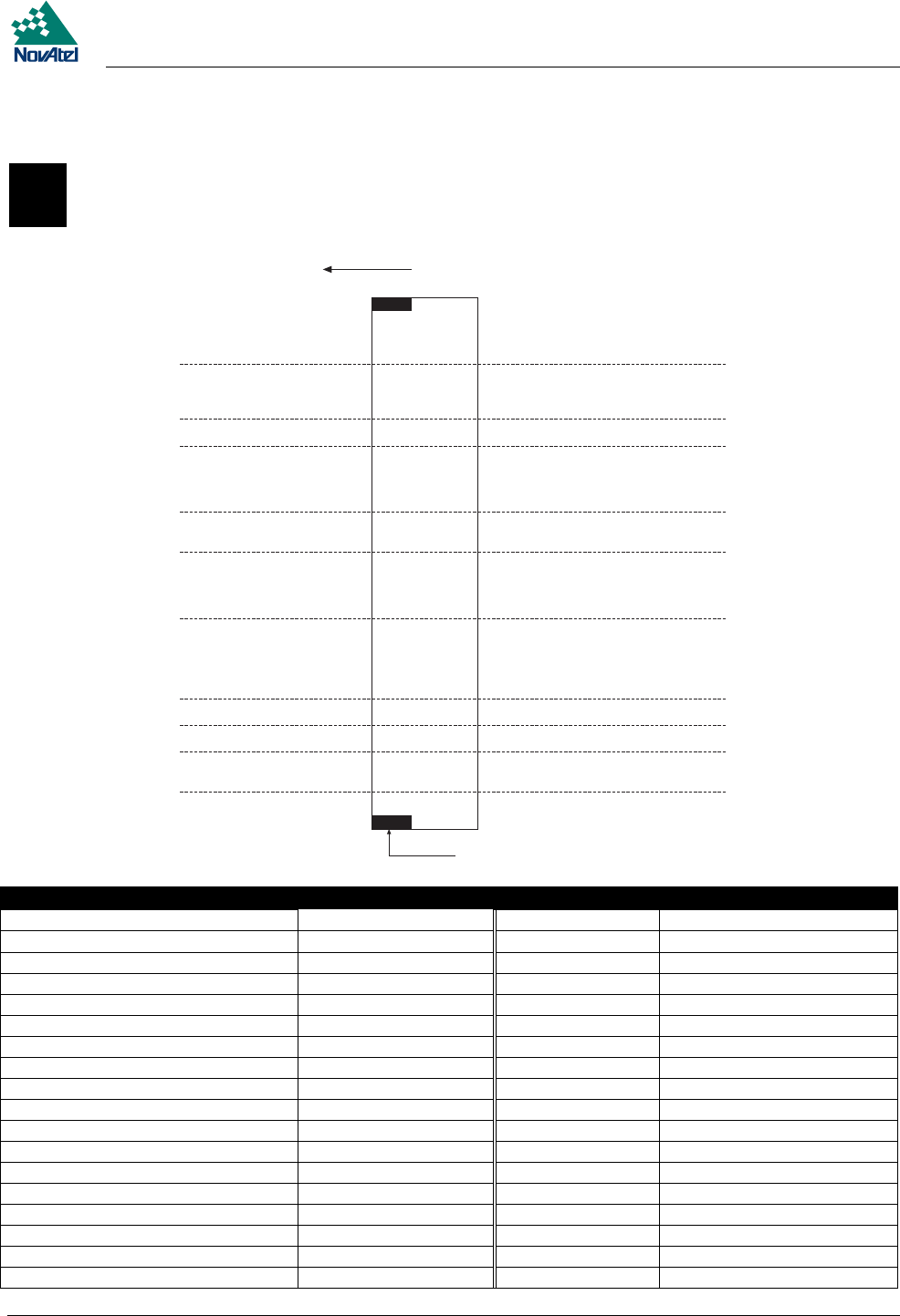
E Edge-View Of Connector P1
MiLLennium GPSCard and Enclosures Guide to Installation & Operation 65
E EDGE-VIEWOF CONNECTOR P1
E EDGE-VIEW OF CONNECTOR P1
■ ■
■ ■
■ ■
■ ■
■ ■
■ ■
■ ■
■ ■
■ ■
■ ■
■ ■
■ ■
■ ■
■ ■
■ ■
■ ■
■ ■
■ ■
■ ■
■ ■
■ ■
■ ■
■ ■
■ ■
■ ■
■ ■
■ ■
■ ■
■ ■
■ ■
■ ■
■ ■
1
2
3
4
5
6
7
8
9
10
11
12
13
14
15
16
17
18
19
20
21
22
23
24
25
26
27
28
29
30
31
32
BA
34
35
36
37
40
42
38
39
41
43
33
Pin Number Description Pin Number Description
1A, 1B, 4A, 7A,15A, 21A-32A GND 19A DCD2
2A, 2B Vcc 19B DSR2
3A, 5B-8B, 12A, 12B-16B, 20A, 20B N/C 21B VARF
3B Reserved for future use 22B PPS
4B External LNA Power 23B Measure Out
5A, 6A, 13A, 14A, 26B, 27B, 30B-32B Factory Use 24B Mark In
8A DTR 1 25B Status
9A TXD1 28B Reset In
9B CTS1 29B Reset Out
10A RXD1 33 Component Side of GPSCard
10B RTS1 34 Power
11A DCD1 35, 37, 40, 42 Factory Use
11B DSR1 36 COM1 (RS-232C)
16A DTR2 38 COM2 (RS-232C)
17A TXD2 39 Strobes
17B CTS2 41 Control
18A RXD2 43 Keying Tab
18B RTS2
