Chapter 1 5
Graphics contained within this publication are for representation only.
Connections & Setup
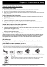
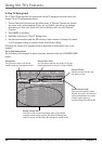
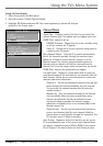
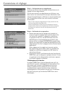
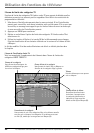
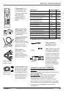
Explanation of Jacks
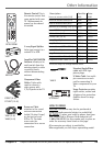
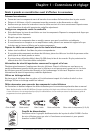
This section describes the jacks you can use to make connections. There are several
ways to connect components to your TV.
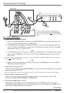
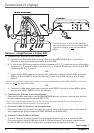
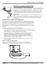
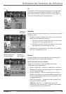
G-LINK Connect the end of the G-LINK cable (provided) to this jack. The G-LINK
cable enables the TV’s Guide Plus+ system to interact with the cable box and/or the
VCR. A picture of the G-LINK cable is on page 3.
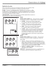
CABLE/ANTENNA Lets you connect a coaxial cable to receive the signal from the
antenna, cable or cable box.
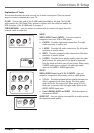
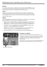
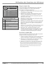
INPUT1
VIDEO, AUDIO R and L INPUTS Lets you connect a
component such as a VCR or DVD player.
• R AUDIO Provides right audio connection. The right
audio connector is usually red.
• L AUDIO Provides left audio connection. The left audio
connector is usually white.
• VIDEO Provides composite video connection. The video
connector is usually yellow.
• S-VIDEO Provides better picture quality than the video
jacks because the color part of the signal is separated
from the black and white part of the picture. When using
S-VIDEO, make sure to connect left and right audio
cables to the INPUT1 AUDIO Input jacks.
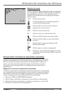
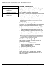
INPUT2
VIDEO, AUDIO R and L and Y, Pb, Pr
INPUTS Lets you
connect a component video source, such as a DVD player.
• Y, Pb, Pr Provides optimum picture quality because the
video is separated into three signals. Use three video-
grade cables for the connection. When using Y, Pb, Pr,
make sure to connect left and right audio cables to the
INPUT2 AUDIO Input jacks.
• R and L/MONO AUDIO and VIDEO Their description is
the same as INPUT1.
AUDIO OUT Lets you connect an amplifier or audio receiver
for improved sound quality.
S-VIDEO
R-AUDIO-L
VIDEO
INPUT1
P
R
P
B
R-AUDIO-L
VIDEO
Y
INPUT2
RL
AUDIO
OUT