3
4 6 7 85
1
2
6
Introduction (continued)
Components (continued)
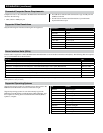
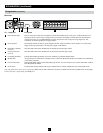
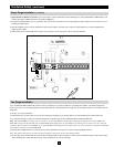
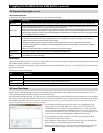
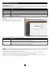
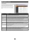
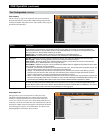
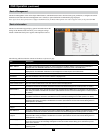
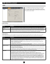
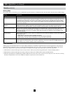
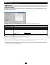
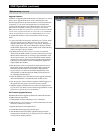
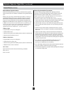
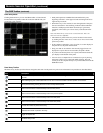
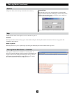
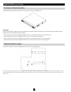
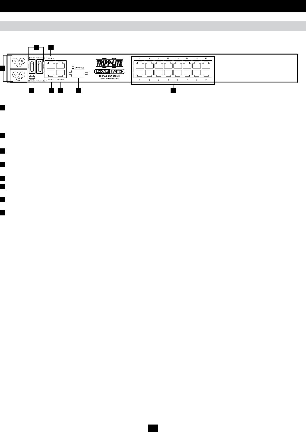
Rear View
No. Component Description
1
Power Sockets (C6) The two C6 power sockets are located here. Connect the included power cords (C5 to 5-15P) from here to an
appropriate power source. Note: To help protect your system from sudden, transient increases and decreases
in electrical power, it is recommended that you plug your devices into a Tripp Lite surge suppressor, line
conditioner or uninterruptible power supply (UPS).
2
Power Switchs The On/Off switches for the two power supplies are here. They are marked 1 and 2. Switch 1 is for the power
supply on the top and switch 2 is for the power supply on the bottom.
3
Secondary LAN Port
(LAN 2)
The cable that connects the KVM switch to the backup network plugs in here.
4
Primary LAN Port
(LAN 1)
The cable that connects the KVM switch to the primary network plugs in here.
5
Grounding Terminal Connect the included grounding wire to this terminal to ground the KVM switch.
6
Modem Port An optional dial-in connection is available for use in the event the KVM switch is not available over the Primary
or Secondary networks.
7
Local Console Port The included USB – PS/2 Console Cable Kit plugs in here. You can connect a local console with either a USB or
PS/2 Keyboard and Mouse.
8
Server Ports Cat5e/6 cable connects between these ports and the SIUs to connect computer/servers to the KVM switch.
Note: The figure above shows the rear panel of a B064-032-04-IPG or B064-032-02-IPG. The B064-016-04-IPG and B064-016-02-IPG differ
in that it only has a single block of 16 KVM ports.