6
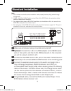
Standard Installation
7
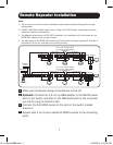
Repeatstep6toconnectadditionalB126-Seriesremotereceiver
units to the remaining ports.
8
B126-1A0 and B126-1A0-WP-1 only:Connecttheexternalpower
supplytotheactiveremotereceiverunit,andplugitintoaTrippLite
SurgeSuppressor,PDUorUPS.Whenreceivingpower,theGreen
RJ45LEDontheB126-1A0,andtheGreenPowerLEDonthe
B126-1A0-WP-1,willilluminate.
9
Repeatstep8foreachadditionalactiveremotereceiverunitinthe
installation.
10
ConnecttheremotereceiverunittoamonitorusingaTrippLiteP568-
SeriesHigh-SpeedHDMIcable.IfyouhaveaB126-1P0,connectits
built-inHDMIconnectortoamonitor.Whenconnectedtoand
receivingpowerfromamonitor,theGreenRJ45LEDontheB126-1P0,
andtheGreen PowerLEDontheB126-1P0-WP-1,willilluminate.
11
Repeat step 10 for each additional remote receiver unit in the
installation.
12
Turnonthepowertotheconnecteddevices.TheOrangeRJ45LEDs
ontheB126-2X2,B126-4X4andB126-1A0,andtheOrangeActivity
LEDontheB126-1A0-WP-1,willilluminate.Thevideoimageshould
nowbedisplayedontheconnectedmonitors.
13
B126-1A0andB126-1A0-WP-1only:Ifnecessary,usethe
Equalization control to adjust the video image.
Note: An improper Equalizationsetting can cause the monitor not to display an image at all.
Try each setting until an acceptable image is displayed.
14
Presstheswitchnexttoeachsetof Output LEDstoswitchthesource
beingdisplayedonthecorrespondingOutput monitor. You can also
usetheincludedremotecontroltoswitchbetweensources.Aswith
theswitchnexttotheOutputLEDs,pressthebuttonontheremote
control of the desired Outputporttoswitchthesourcebeingdisplayed.
Note: The same 4 button remote control comes with both the B126-2X2 and B126-4X4.
Buttons 3 and 4 will not be used for the B126-2X2.
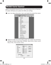
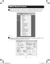
SeetheRS232 Serial Control section in this manual for details on
controllingtheswitchusingTerminalEmulationSoftware.
13-11-140 93-32BB.indd 6 11/19/2013 4:57:41 PM