


2-Port 1000BASE-SX and 2-Port 1000BASE-LX Gigabit Ethernet Interface Modules Quick Start Guide
13
7
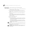
To engage the module connectors and the chassis backplane
connectors, apply forward pressure to the module front panel.
You feel a slight resistance as the connectors engage.
CAUTION:
If the resistance is too great, the module connectors and
the backplane connectors may not be aligned. Forcing the module into
place can damage the module connectors and backplane connectors. If
necessary, remove and reinsert the module, ensuring that the
connectors are properly aligned. Do not tighten the spring-loaded
screws to seat the module.
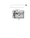
If modules are already installed to the left of this module in a 16-slot
chassis or installed beneath this module in a 7-slot chassis, you may
need to apply sideways or downward pressure on that adjacent module
to have your module line up correctly in its slot. Applying this pressure
compresses the thin strip of rubber-like material (which exists for
electromagnetic interference purposes) at the edge of the front panel
of the adjacent module.
8
Ensure that the module remains fully seated in the backplane
connectors while you close the ejector handles.
Use one hand to hold the module in place, and use your other hand to
close one ejector handle at a time until the handles are parallel with
the front panel.
9
To secure the module front panel to the chassis, tighten the
spring-loaded screws to a torque specification of 3–5 inch-pounds.
CAUTION:
To ensure adequate cooling air flow and continued product
safety agency compliance, install blank faceplates over all empty slots.