


15
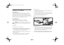
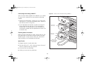
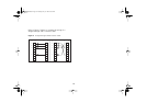
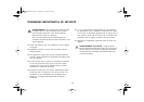
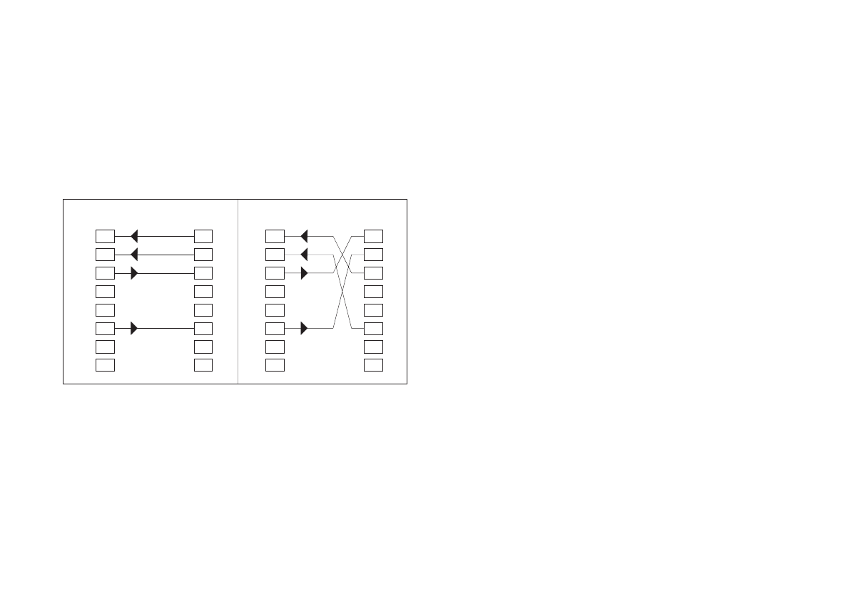
Refer to Figure 5 below to compare the wiring of a
straight-through and a crossover cable.
Figure 5
Straight-through Cable/Crossover Cable
1
Normal
port
Pin Pin
Uplink
port
Rx+
Rx-
Tx+
Tx-
Rx-
Rx+
Tx-
Tx+
2
3
4
5
6
7
8
1
2
3
4
5
6
7
8
1
Normal
port
Pin Pin
Normal
port
Rx+
Rx-
Tx+
Tx-
Rx+
Rx-
Tx+
Tx-
2
3
4
5
6
7
8
1
2
3
4
5
6
7
8
3C16702.book Page 15 Tuesday, July 13, 1999 10:16 AM