


48 CHAPTER 2: INSTALLING THE SWITCH 7750
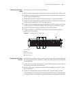
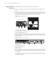
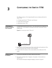
Follow the parameters defined in Table 48 for binding cables with ties.
Post-installation
Checklist
After you install your switch, use the checklist in Table 49 to verify that your switch
operates correctly.
WARNING: Confirm that you have turned off the power before checking your
installation. Improper connections can injure people or damage components of
the switch.
Table 48 Cable Binding Parameters
Cable Bundle Diameter Space Between Bundles
10 mm (0.5in) 80-150 mm (3.5 – 6 in)
10-30 mm (.5 – 1.2 in) 150-200 mm (6 – 8 in)
30 mm (1.2 in) 200-300 mm (8 – 12 in)
Table 49 Installation Checklist
Item Normal Abnormal (Remarks)
Antistatic wrist strap
Console cable
Ground wire
Power cord
Fabric
I/O module
Fan frame