


1-4 CHAPTER 1: INTRODUCTION
Hardware
Description
The following sections describe the system hardware components.
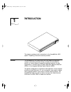
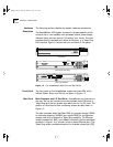
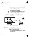
The AccessBuilder 4000 system consists of a chassis assembly which
contains one of two available main processor boards, power supply,
indicator lights, and two slots for I/O cards of your choice. The main
processor board is available with either an Ethernet, or a Token Ring
LAN interface. Figure 1-2 shows the front and back of the system.
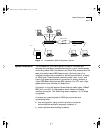
Figure 1-2 The AccessBuilder 4000 Front and Rear Panels
Front Panel The front panel of the AccessBuilder chassis has three LEDs, which
indicate Power, Status, and Activity, as shown in Figure 1-2.
Rear Panel Main Processor and I/O Card Slots. AccessBuilder has three slots in
the rear. The top slot contains the main processor board (Ethernet or
Token Ring) and the two smaller slots below are for the I/O cards. The
position of the slots and their numbering scheme are also shown in
Figure 1-2.
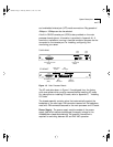
The main processor board has Flash ROM for program storage, DRAM
for software operation, NVRAM (non-volatile RAM) for configuration
storage, and built-in Ethernet or Token Ring capability. The Ethernet
version provides AUI, BNC, and 10BaseT connectors (switch selectable),
as shown in Figure 1-3 to connect to the on-board Ethernet port. The
Token Ring version provides connectors for shielded twisted pair (STP),
SLOT 2 SLOT 1
CONSOLE
110-240 VAC
50-60 Hz 1A
STP
4M/16M
UTP
TOKEN RING
110-240 VAC
50-60 Hz 1A
CONSOLE
AUI
BNC
TPE
BNC/AUI/TPE
ETHERNET
SLOT 2 SLOT 1
StatusActivity Power
SYSTEM STATUSSYSTEM STATUS
AccessBuilder
4000
Remote Access Server
Front Panel
Rear Panel Token Ring
Rear Panel Ethernet
ab4kbook Page 4 Thursday, March 27, 1997 11:51 AM