


14 CHAPTER 1: INTRODUCING THE 3COM SWITCH 4050 AND 4060
3Com Switch 4050
and 4060 — Front
View Detail
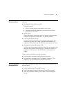
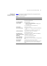
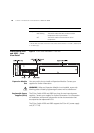
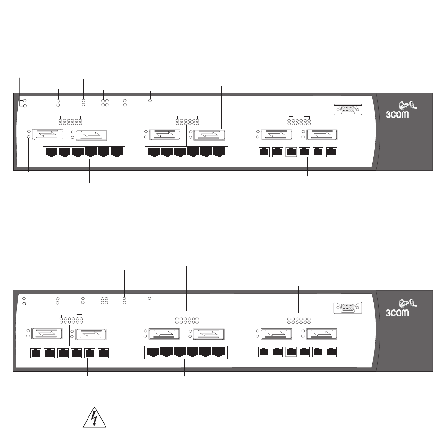
Figure 1 3Com Switch 4050 — front view
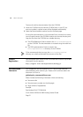
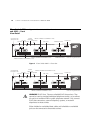
Figure 2 3Com Switch 4060 — front view
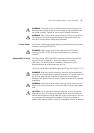
WARNING: RJ-45 Ports. These are shielded RJ-45 data sockets. They
cannot be used as standard traditional telephone sockets, or to connect
the unit to a traditional PBX or public telephone network. Only connect
RJ-45 data connectors, network telephony systems, or network
telephones to these sockets.
Either shielded or unshielded data cables with shielded or unshielded
jacks can be connected to these data sockets.
P
S
GBIC 1
P
S
GBIC 2
P
S
GBIC 4
P
S
GBIC 3
P
S
GBIC 6
P
S
GBIC 5
1000SX
P
S
19
20
21 22 23 24
19
20
21
22
23
24
10/100/1000
P
S
13
14
15 16 17 18
13
14
15
16
17
18
3Com Switch 4050
3C17708
UNIT STATUS
LAYER 3
2
PSU
1
FANS
R
F
1
2
UNIT
3
4
S
P
MODULE
TEMP
Unit Status LED
and Layer 3 LED
PSU LEDs
Fan LEDs
Unit LEDs
Module
Status LEDs
Temperature
LED
Yellow = 10/100Mbps Green = 1000Mbps On = enabled, link OK Flashing = disabled
P = Packet
S = Status
GBIC Ports
1000BASE-SX LEDs
Console Port
Front Fan Tray (behind door)
1000BASE-SX Ports
10BASE-T/100BASE-TX/1000BASE-T Ports
GBIC LEDs
10BASE-T/100BASE-TX/1000BASE-T LEDs
10/100/1000
P
S
13
14
15 16 17 18
13
14
15
16
17
18
10BASE-T/100BASE-TX/1000BASE-T Ports
P
S
GBIC 1
P
S
GBIC 2
P
S
GBIC 4
P
S
GBIC 3
P
S
GBIC 6
P
S
GBIC 5
1000SX
P
S
7
7
8
8
9
9
10
10
11
11
12
12
1000SX
P
S
19
20
21 22 23 24
19
20
21
22
23
24
10/100/1000
P
S
13
14
15 16 17 18
13
14
15
16
17
18
3Com Switch 4060
3C17709
UNIT STATUS
LAYER 3
2
PSU
1
FANS
R
F
1
2
UNIT
3
4
S
P
MODULE
TEMP
Unit Status LED
and Layer 3 LED
PSU LEDs
Fan LEDs
Unit LEDs
Module
Status LEDs
Temperature
LED
Yellow = 10/100Mbps Green = 1000Mbps On = enabled, link OK Flashing = disabled
P = Packet
S = Status
GBIC Ports
1000BASE-SX LEDs
Console Port
Front Fan Tray (behind door)
1000BASE-SX Ports
10BASE-T/100BASE-TX/1000BASE-T Ports
1000BASE-SX Ports
GBIC LEDs
10BASE-T/100BASE-TX/1000BASE-T LEDs