


22 CHAPTER 2: INSTALLING THE SWITCH
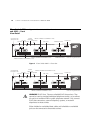
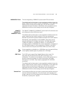
Package Contents ■ 3Com Switch 4050 (3C17708) or Switch 4060 (3C17709)
■ CD-ROM
■ This Guide
■ Management Quick Reference Guide
■ Release Notes
■ Warranty Flyer
■ Power Cord
■ 2 x securing brackets
■ 8 x screws
■ 4 x rubber feet
Choosing a Suitable
Site
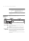
The 3Com Switch 4050 and 4060 are suited for use in an internal wiring
closet, a network room, or telecommunications room, where they can be
mounted in a standard 19-inch equipment rack, or free-standing.
CAUTION: Ensure that the ventilation holes are not obstructed.
To ensure these products provide optimum performance, high speed fans
are used to provide ventilation. These fans have a high audible output.
When deciding where to position the Switch, ensure that:
■ Cabling is located away from:
■ sources of electrical noise such as radios, transmitters and
broadband amplifiers.
■ power lines and fluorescent lighting fixtures.
■ The Switch is accessible and cables can be connected easily.
■ Water or moisture cannot enter the case of the Switch.
■ Air flow is not restricted around the Switch or through the vents in the
side of the Switch. 3Com recommends that you provide a minimum of
25 mm (1 in.) clearance.
■ Air temperature around the Switch does not exceed 40 °C (104 °F).
If the Switch is installed in a 19-inch rack or closed assembly its local air
temperature may be greater than room ambient temperature.