


Designing and Expanding the Network 2 - 11
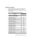
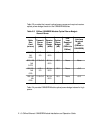
Table 2-6 shows the range of loss and the typical loss as a result of splices.
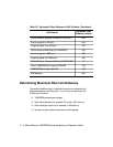
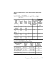
Optical Fiber Loss
Even though fiber optic cable can carry light signals over a long distance,
optical power loss is a significant factor. Check your cable manufacturer's
rating of the loss characteristic of your fiber cable to determine the actual
loss.
Table 2-7 shows typical power losses in fiber optic cables.
Table 2-6. Connector and Splice Insertion Loss
Connector Type Range of Loss Per Pair (dB)
Typical Loss
(dB)
SMA Patch Panel 1.0 to 3.0 2.0
ST or FC Patch Panel 0.1 to 0.75 0.5
Splice Type Range of Loss (dB)
Typical Loss
(dB)
Fusion 0.01 to 0.1 0.05
Mechanical 0.2 to 1.0 0.5
Table 2-7. Typical Fiber Loss Characteristics
Fiber Type Loss (dB/km)
Typical Loss
(dB/km)
50/125 micron @ 820 nM 3 to 5 3.75
62.5/125 micron @ 820 nM 3 to 5 3.75
85/125 micron @ 820 nM 3 to 6 4.0
100/140 micron @ 820 nM 3 to 6 5.0