


Designing and Expanding the Network 2 - 25
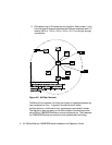
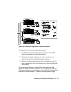
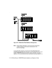
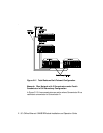
To determine if the configuration meets Ethernet distance limitations for
Transceivers A and B:
1. Use 4200 m as the maximum network diameter for a pure fiber
network as defined by the 802.3 specification (Rule 3).
2. Subtract the fiber equivalent distance of 420 m for the signal entering
the 10BASE-T Module from Transceiver B and 50 meters for the signal
exiting the 10BASE-FB Module within the same concentrator (Rule 4).
3. Subtract the fiber equivalent distance of 190 m for the signal
entering the 10BASE-FB Module in the top concentrator, and exiting a
different port on the same 10BASE-FB Module.
4. Subtract the fiber equivalent distance (800 m) of the IEEE Repeater
(Rule 4).
Note: In the reverse direction, a signal originating at Transceiver
A loses 165 m of fiber equivalent distance when it exits the
10BASE-T Module to which Transceiver B is connected and
140 meters for the signal entering the 10BASE-FB Module in
the lower concentrator. Because the overall fiber
equivalence of the path is greater for signals going from
Transceiver B to A, the fiber equivalence of this path
determines whether the link meets the 4200 m Ethernet
link maximum.
5. Subtract the sum of intervening cable lengths:
150 m + 50 m + 200 m + 2000 m + 100 m = 2500 m
6. The remainder is 4200 m - 420 m - 50 m - 190 m - 800 m - 2500 m =
240 m.