


The Power-up Sequence 25
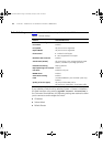
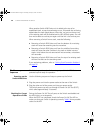
Table 6 Power/Self Test LED colors
In addition, check the Unit LEDs on all Switches in the stack. If a Unit LED
is off, initialization is not complete. 3Com recommends that you do not
use the Switch's management interface until the Unit LED is green.
If there is evidence of a problem, see “Solving Problems Indicated by
LEDs” on page 54.
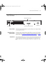
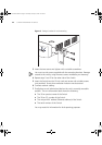
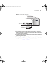
Connecting a
Redundant Power
System
You can connect a SuperStack Advanced Redundant Power System
(3C16071, 3C16071A or 3C16071B) to the Switch. This unit, which is
also known as an RPS, is designed to maintain the power to your Switch
if a power supply failure occurs.
For normal redundancy, the unit requires one Type 2A Power Module
(part number 3C16074A). For full redundancy, the unit requires two type
2A Power Modules combined using a Type 2 Y-Cable (part number
3C16078).
CAUTION: The Switch has no ON/OFF switch; the only method of
connecting or disconnecting mains power is by connecting or
disconnecting the power cord.
CAUTION: The Switch can only use a SuperStack Advanced Redundant
Power System output.
Choosing the Correct
Cables
All of the ports on the front of the Switch 4200 Series are Auto-MDIX,
that is they have a cross-over capability. The port can automatically detect
whether it needs to operate in MDI or MDIX mode. Therefore you can
make a connection to a port with a straight-through (MDI) or a cross-over
cable (MDIX).
The Auto-MDIX feature only operates when auto-negotiation is enabled.
If auto-negotiation is disabled, all the Switch ports are configured as
MDIX (cross-over). If you want to make a connection to another MDIX
Color State
Green The Switch is powered-up and operating normally.
Yellow The Switch has failed its Power On Self Test.
Off The Switch is not receiving power.
DUA1730-0AAA02.book Page 25 Thursday, January 23, 2003 12:28 PM