


User Manual
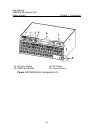
PSE2500-A3 External PoE
Power System Chapter 2 System Description
2-4
rectifier failure, rectifier self-protection, the red LED is on. Once the
alarm is gone, the red LED goes off.
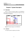
The controller of the PSE2500-A3 has two major functions:
I. Monitoring the system operation status
Inside PSE2500-A3 there is an AC sensor card, which can
sample the AC input voltage. The sampled signal is sent into the
controller for data processing. Once the input voltage is lower than the
pre-set alarm level of the input low voltage, the controller reports an
AC input under-voltage alarm. Likewise, if the input voltage is higher
than the pre-set alarm level of the input high voltage, the controller
reports an AC input over-voltage alarm.
The sampled DC output voltage signal is also sent into the
controller. Once the output voltage is lower than the pre-set alarm
level of the output low voltage, the controller will reports a DC Low
alarm. Likewise, if the output voltage is higher than the pre-set alarm
level of the output high voltage, the controller reports a DC output high
alarm.
The rectifier communicates with the controller through RS485
bus. The working status of the rectifier is passed to the controller in
this way. Once the rectifier has an alarm, the information is passed to
the controller. The rectifier failure alarm includes: AC input failure, DC
output failure, fan failure, output high, over temperature, and module
shut-down.
II. Communicate with deamon systems
The controller supports China national standard protocol YD/T
1104-2001. User can apply this protocol to read system information or