


Table Of Contents
Chapter 1. Introduction ..........................................................................1-1
1-1. Features & Specifications ........................................................................1-1
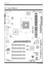
1-2. Layout Diagram .......................................................................................1-3
Chapter 2. Hardware Setup....................................................................2-1
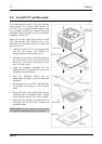
2-1. Install The Motherboard...........................................................................2-1
2-2. Install CPU and Heatsink.........................................................................2-2
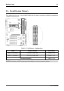
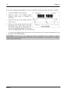
2-3. Install System Memory............................................................................2-3
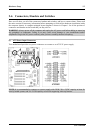
2-4. Connectors, Headers and Switches..........................................................2-5
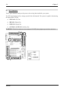
(1). ATX Power Input Connectors........................................................2-5
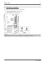
(2). FAN Connectors.............................................................................2-6
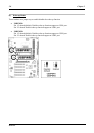
(3). CMOS Memory Clearing Header..................................................2-7
(4). Wake-up Header.............................................................................2-8
(5). Front Panel Switches & Indicators Headers ..................................2-9
(6). Additional USB Port Headers......................................................2-10
(7). Front Panel Audio Connection Header ........................................2-11
(8). Internal Audio Connectors...........................................................2-12
(9). Accelerated Graphics Port Slot....................................................2-13
(10). Floppy Disk Drive Connector......................................................2-14
(11). IDE Connectors............................................................................2-15
(12). POST Code Display.....................................................................2-16
(13). Serial ATA Connectors.................................................................2-17
(14). Status Indicators...........................................................................2-18
(15). System Management Bus Headers...............................................2-19
(16). Back Panel Connectors ................................................................2-20
Chapter 3. BIOS Setup............................................................................3-1
3-1. µGuru Utility............................................................................................3-3
3-2. Standard CMOS Features.........................................................................3-9
3-3. Advanced BIOS Features.......................................................................3-12
3-4. Advanced Chipset Features....................................................................3-14
3-5. Integrated Peripherals ............................................................................3-18
3-6. Power Management Setup .....................................................................3-21
3-7. PnP/PCI Configurations.........................................................................3-24
3-8. Load Fail-Safe Defaults .........................................................................3-26
3-9. Load Optimized Defaults.......................................................................3-26
User’s Manual