


Chapter 3 43
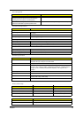
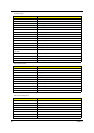
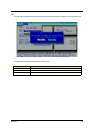
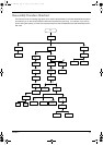
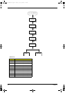
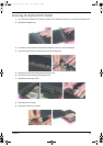
Disassembly Procedure Flowchart
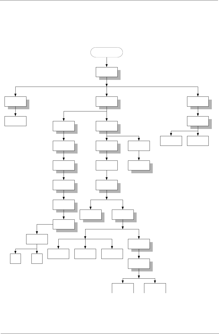
The flowchart on the succeeding page gives you a graphic representation on the entire disassembly sequence
and instructs you on the components that need to be removed during servicing. For example, if you want to
remove the system board, you must first remove the keyboard, then disassemble the inside assembly frame in
that order.
Start
Battery
RAM Door Middle Cover HDD Module
Memory
Fx1
Kx4
Keyboard
Fx3
Cx2
HDD Tray
HDDHDD FPC
Hinge Covers/
L&R
L:Fx2
R:Fx1
Dx4
14.1" LCD
Module
Fan
Dx3
Optical Drive
Thermal
Module w/
heatsink
Ex4
Ex1
Fx1
ODD Bracket
Gx2
CPU
FDD FFC FDD
Upper Case
w/ touchpad
Dx1
Cx3
Cx13
Lower Case
Assy
Top Cover
Shielding
FDD Module
Fx4
Lower CaseMain Board
LCD Bezel
Fx6
Inverter Board
LCD Hinges
Cx4
LCD Panel
Fx4
LCD Brackets
LCD
Cable
Lx4
LCD
Ax4
Fx4
Fx3
FDD Holder
Jx3
Aspire 1300.book Page 43 Friday, July 26, 2002 1:41 PM