


66 Chapter 3
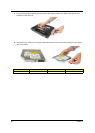
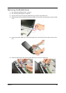
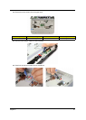
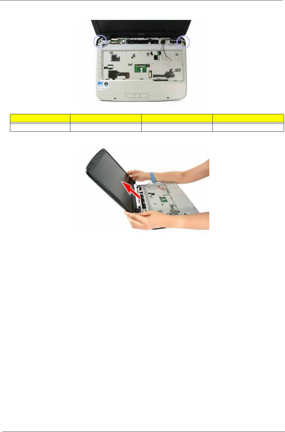
9. Remove the two screws (F) from the left and right hinge of the LCD module.
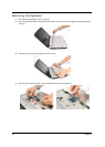
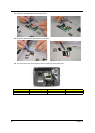
10. Carefully remove the LCD module from the base unit.
NOTE: Make sure the cables are routed well before connecting the cables back to the unit.
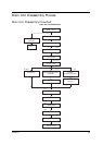
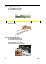
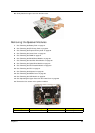
Separating the Upper Case from the Lower Case
1. See “Removing the Battery Pack” on page 51.
2. See “Removing the SD Dummy Card” on page 52.
3. See “Removing the Express Dummy Card” on page 52.
4. See “Removing the Lower Cover” on page 53.
5. See “Removing the DIMM” on page 54.
6. See “Removing the WLAN Board Module” on page 55.
7. See “Removing the Hard Disk Drive Module” on page 56.
8. See “Removing the Optical Drive Module” on page 57.
9. See “Removing the CPU Heatsink Module” on page 60.
10. See “Removing the CPU” on page 61.
11. See “Removing the Keyboard” on page 62.
12. See “Removing the Middle Cover” on page 63.
13. See “Removing the LCD Module” on page 64.
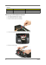
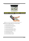
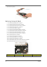
Step Size (Quantity) Color Torque
1~2 M2.5 x L8 (2) Black 4.0 kgf-cm