


48 Chapter 3
External Module Disassembly Process
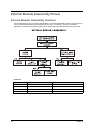
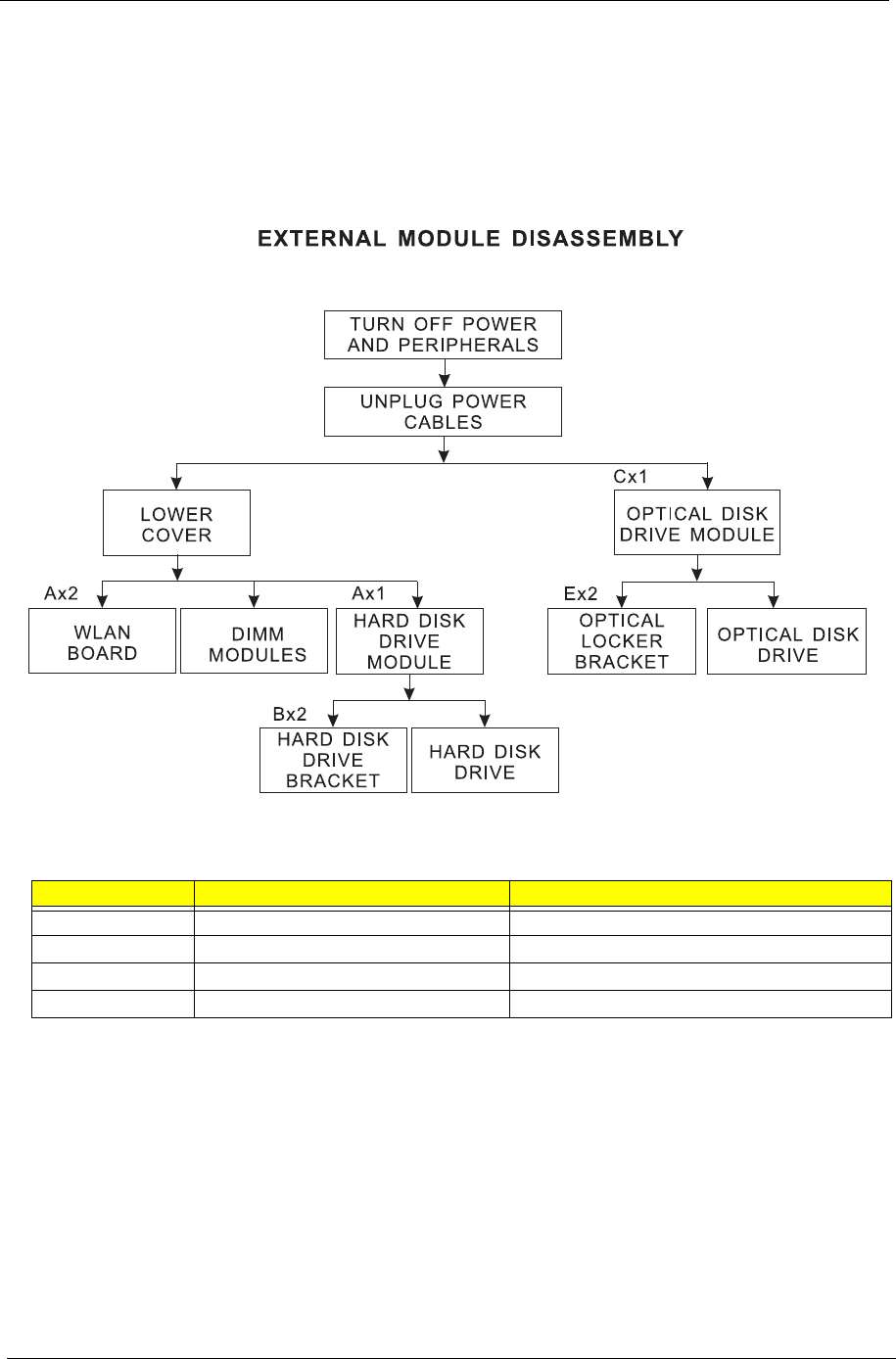
External Modules Disassembly Flowchart
The flowchart below gives you a graphic representation on the entire disassembly sequence and instructs you
on the components that need to be removed during servicing. For example, if you want to remove the
mainboard, you must first remove the keyboard, then disassemble the inside assembly frame in that order.
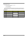
Screw List
Item Screw size Part No.
A M2 x L4 86.00F24.724
B M3 x L4 86.9A554.4R0
C M2 x L6 86.00F58.726
E M2 x L2.5 86.00F22.722