


Chapter 3 53
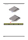
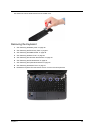
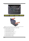
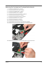
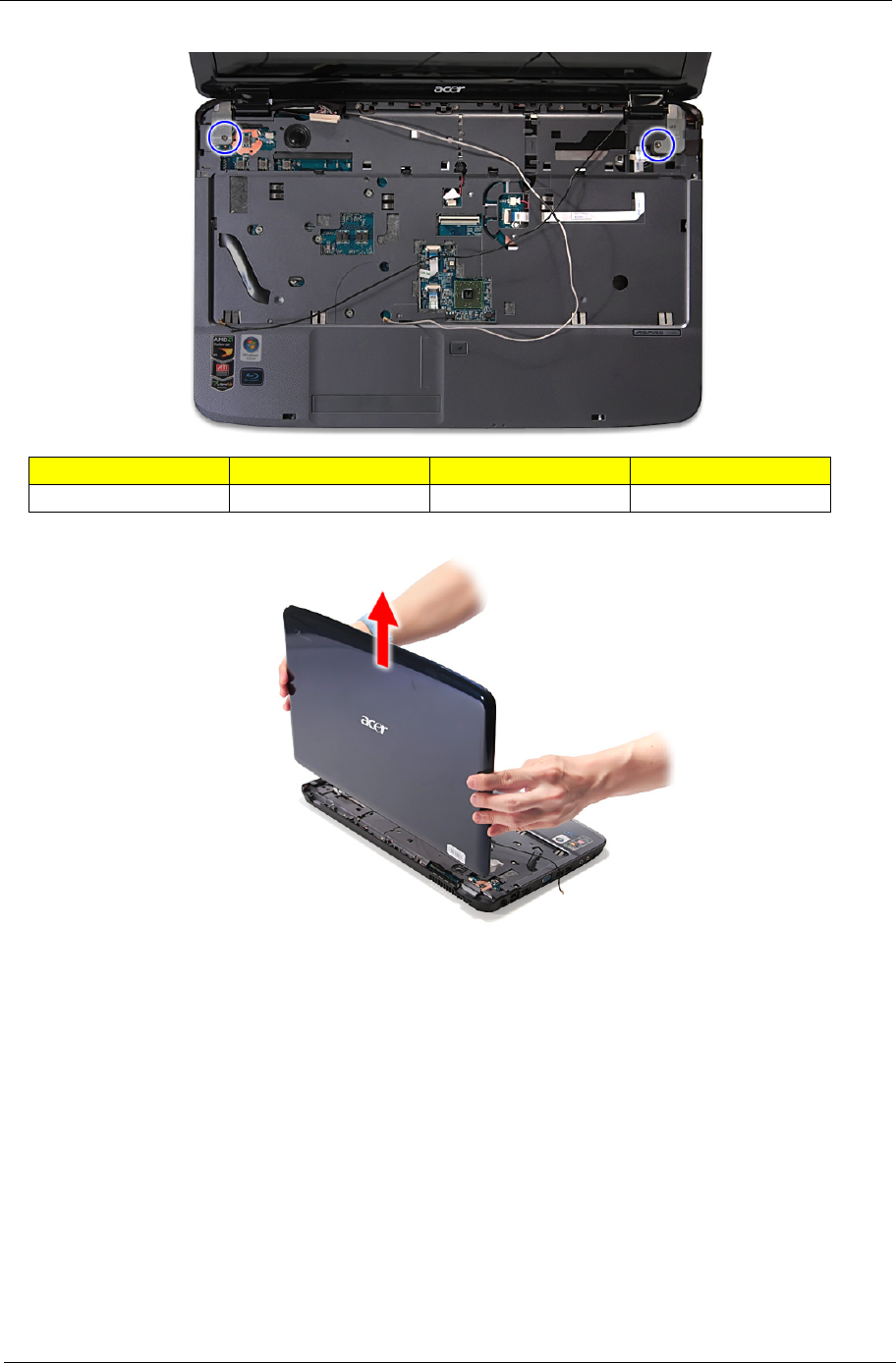
15. Remove the two screws (G) from the left and right hinge of the LCD module.
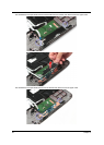
16. Carefully remove the LCD module from the base unit.
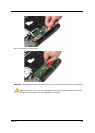
NOTE: When connecting the cable back to the unit, please note that the cable should be routed well.
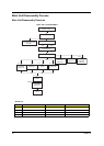
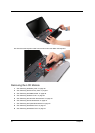
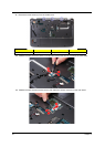
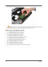
Separating the Upper Case from the Lower Case
1. See “Removing the Battery Pack” on page 36.
2. See “Removing the SD Dummy Card” on page 37.
3. See “Removing the DIMM Module” on page 38.
4. See “Removing the Back Cover” on page 39.
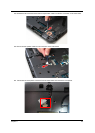
5. See “Removing the Hard Disk Drive Module” on page 40.
6. See “Removing the WLAN Modules” on page 43.
7. See “Removing the Optical Drive Module” on page 44.
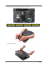
8. See “Removing the Middle Cover” on page 47.
9. See “Removing the Keyboard” on page 49.
10. See “Removing the LCD Module” on page 50.
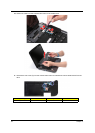
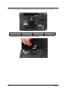
Size (Quantity) Color Torque Part No.
M2.5 x L10 (2) Silver 3.0 kgf-cm 86.1A553.100