


3-7
Disassembly Process 0
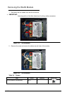
The disassembly process is divided into the following sections:
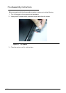
External components disassembly
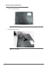
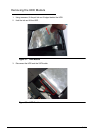
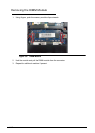
Main unit disassembly
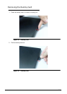
LCD module disassembly
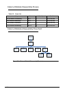
The flowcharts provided in the succeeding disassembly sections illustrate the entire
disassembly sequence. Observe the order of the sequence to avoid damage to any of the
hardware components. For example, when removing the mainboard, remove first the
keyboard, and LCD module then disassemble the inside assembly frame in that order.
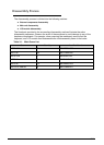
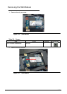
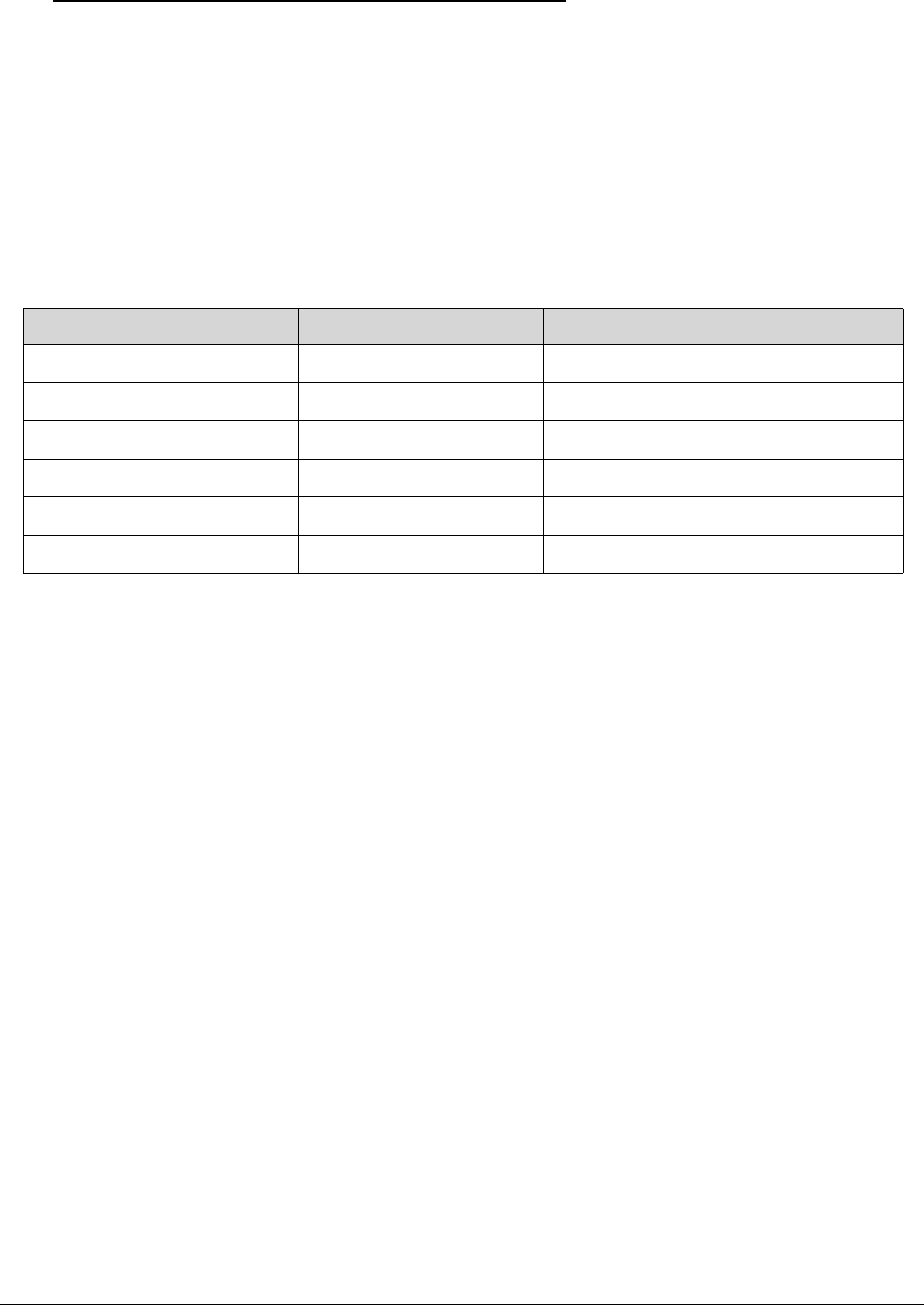
Table 3-1. Main Screw List
Screw Quantity Acer Part Number
M2*2.5 Ni 6 86.W750U.003
M2*3 Ni 35 86.RY8N5.006
M2.5*5 Ni 7 86.B050U.001
M2*2 Ni 5 86.RY8N5.003
M2*6 Ni 10 86.RN60U.002
M2*2L+4.2MM Ni 4 86.RY8N5.001