xiii
List of Figures
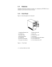
1-1 Front Panel.......................................................................................................1-2
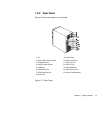
1-2 Rear Panel........................................................................................................1-3
1-3 Connecting the Keyboard..............................................................................1-4
1-4 Connecting the Monitor.................................................................................1-5
1-5 Connecting the Mouse ...................................................................................1-6
1-6 Connecting the Parallel Printer.....................................................................1-7
1-7 Complete System Connections .....................................................................1-8
1-8 Connecting Multimedia Components..........................................................1-9
1-9 Connecting the Telephone Line and Handset to the Fax/Modem ........1-10
2-1 System Board Layout.....................................................................................2-4
2-2 Jumper and Connector Locations.................................................................2-5
4-1 Removing the ScrewsREMOVING THE SCREWS ....................................4-4
4-2 Removing the Housing Cover.......................................................................4-4
4-3 Replacing the Housing Cover.......................................................................4-5
4-4 Securing the Screws........................................................................................4-5
4-5 Installing a PCI Card......................................................................................4-6
4-6 Installing an ISA Card....................................................................................4-8
4-7 Installing a DIMM ........................................................................................4-10
4-8 Removing a DIMM.......................................................................................4-11
4-9 Pressing the Latches.....................................................................................4-12
4-10 Removing a Processor Card ........................................................................4-13
4-11 Installing the Retention Mechanism...........................................................4-14
4-12 Removing the Taper Protector from the Fan Sink....................................4-14
4-13 Inserting the Clip Ends into the Processor Holes.....................................4-15
4-14 Locking the Metal Bracket...........................................................................4-15
4-15 Installing a Processor Card..........................................................................4-16
4-16 Locking the Processor ..................................................................................4-16
4-17 Connecting the Fan/Heatsink Cables........................................................4-17


