


Installation
Manual No. 775064 2-5
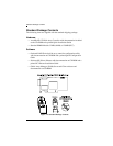
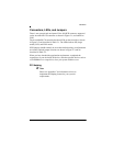
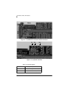
Connectors, LEDs, and Jumpers
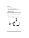
There is one external and one internal Ultra 160 SCSI connector supported
on the AcceleRAID 170 controller as shown in Figure 2-1, and labeled as
CH 0.
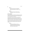
The AcceleRAID 170 controller has three LEDs on the front side as shown
in Figure 2-2 and described in Table 2-1. The LEDs indicate SE (single
ended), LVD, and FAIL modes.
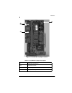
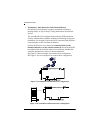
SCSI jumpers should normally be set to their default settings, no adjustments
are needed. Default jumper locations are shown in Figure 2-3 and are
described in Table 2-2.
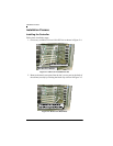
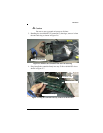
When you have checked the termination requirements, completed the
connections of your desired SCSI devices, and other possible devices such as
a CD-ROM drive or a tape drive, close your system with the cover.
PCI Hotplug
☛ Note
Please see Appendix C for information on how to
implement the Hotplug feature for your system’s
requirements.