Chapter 3 33
Main Unit Disassembly
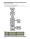
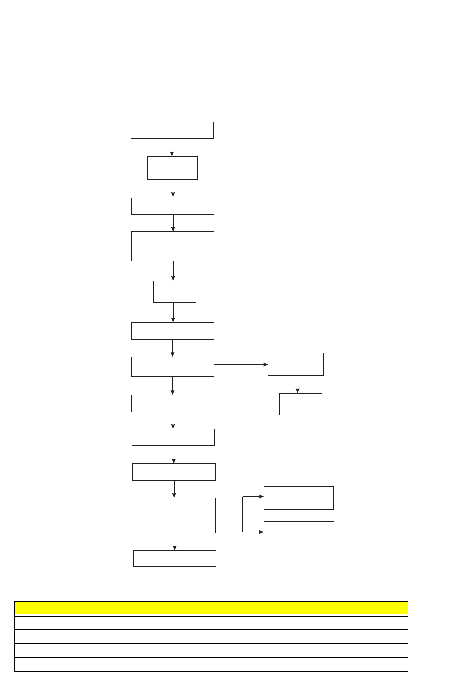
External Modules Disassembly Flowchart
The flowchart below gives you a graphic representation on the entire disassembly sequence and instructs you
on the components that need to be removed during servicing.
Screw List
Screw Part No.
A #6-32 L5 BZN 86.00J07.B60
B #6-32*3/16 NI 86.5A5B6.012
C M3xL5 BZN 86.1A324.5R0
D Hex screw N/A
MAIN UNIT
FRONTBEZEL
MAIN UNIT DISASSEMBLY
SIDEPANEL
CPU
Ax2
HEATSINKFAN
ASSEMBLY
POWERSUPPLY
MEMORYMODULES
PCICARD
FRONTI/OAND
CARDREADERBOARD
BRACKET
MAINBOARD
OPTICALDISKDRIVE
HDD-ODDBRACKET
Ax1
HDDMODULE
HDD
Bx1
Ax4
Ax1
Bx2
Ax6,Cx1
FRONTI/OBOARD
CARDREADER
BOARD
Ax2
Ax2
Dx2


