


46
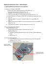
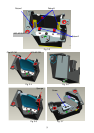
Module Assembly Key Point - Optical Engine
1. Light Pipe Module assembly and overfill alignment
1.1 Assembly LP Module to HSG DMD
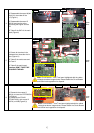
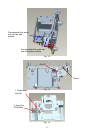
i. Assembly two Overfill adjustment screws to HSG DMD (Fig. 1-1).
** Adjustment criteria refer to below item (Fig. 1-2).
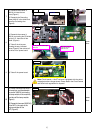
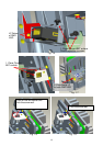
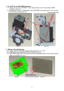
ii. Assembly “Clip LP” and lock with screw well (Fig. 1-3).
iii. Press CLIP of RE_BKT_LP first, and then push it into the hole (Fig. 1-4).
iv. Placed LP Module on LP datum of “DMD HSG” and adjustment screw well, shown
v. (Fig. 1-5).
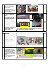
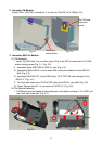
vi. Assembly “Baffle LP” first (Fig. 1-6) & push “Baffle LP” to hook DMD HSG
(Fig. 1-7).
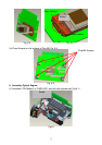
vii. When Lock the screw of Baffle LP, the hand must push the left corner of Baffle LP
before (Fig. 1-8).
viii. Lock the screw of Baffle LP well then release the hand (Fig. 1-9).
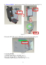
1.2 Overfill Adjustment @ LP Module
Overfill Adjustment Criteria:
i. Pre-assembly 2 adjusting screws. Criteria shown as (Fig.1-2)
ii. Alignment Sequence:
a. To adjust “Horizontal Adjustment Screw” firstly, and then “Vertical Adjustment
Screw”.
b. Refer to Fig. (1-2)
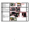
1.3 For Overfill Re-adjustment:
a. Those 2 Adjustment Screws must be released closely to the “Pre-assembly”
positions first (Fig. 1-24-9).
b. ollow adjustment steps shown in Item 1-24.5-ii.
Fig. 1-1
Overfill Vertical
Adjustment Screw
Overfill Horizontal
Adjustment Screw