


The Wireless Connectivity Expert
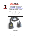
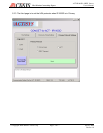
ACT-IR100SD OBEX Server
User’s Manual
4.1 Host Interface Signals
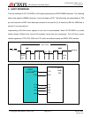
ACT-IR100SD host interface consists of three output signals and five input signals. All these signals are
low active. That is, they are at 0V when active and at VCC level when inactive. When an inverting RS232
level converter is used, the corresponding RS232 level signals are high active. That is, they are at +12V
nominal when active and at –12V nominal when inactive.
4. /TXD: serial data output.
2. /RXD: serial data input.
3. /RTS: output. When hardware flow control is enabled. Active /RTS means /RXD is ready to
receive. Inactive /RTS means /RXD is not ready.
4. /CTS: input. If hardware flow control is enabled, /CTS must be driven active to allow /TXD and
inactive to forbid /TXD. If hardware flow control is disabled, /CTS is optional.
5. /DSR: input. If connection control is enabled, /DSR must be driven active to allow IrDA connection
and inactive to forbid a new connection or terminate an existing connection. If connection control
is disabled, /DSR is optional.
6. /DTR: output. If connection control is enabled, active /DTR means an IrDA connection is made.
Inactive /DTR means there is no connection.
7. /CD: input. Optional.
8. /RI: input. Optional.
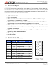
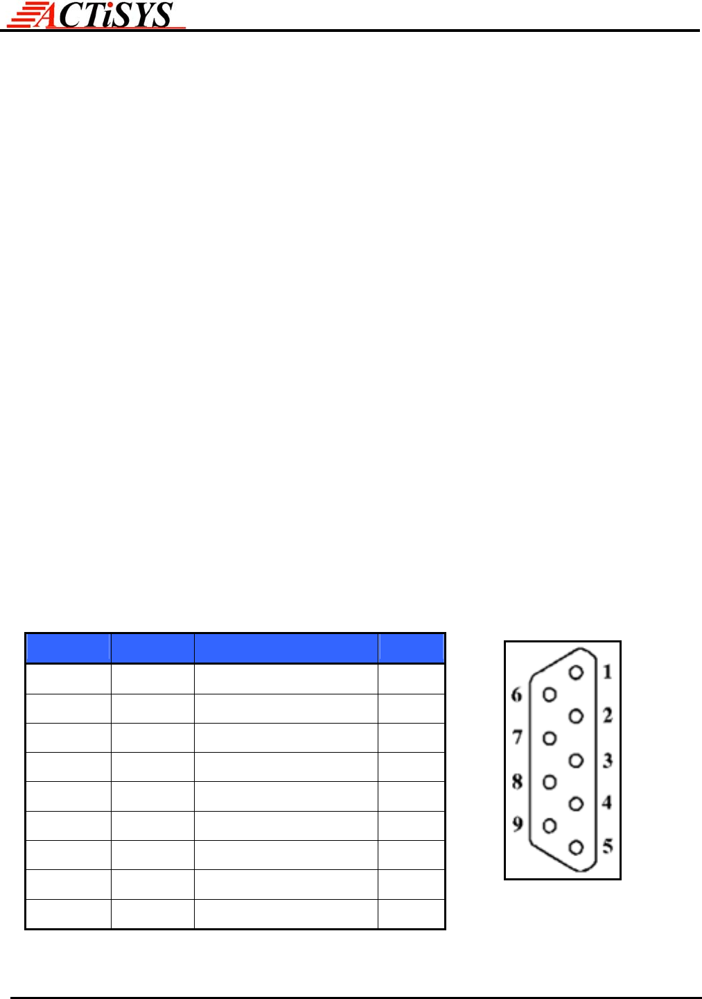
4.2 RS-232C DTE DB-9P Connector
Pin No. Name Descriptions I/O
1 CD
Data Carrier Detect I
2
RXD Receiver Data I
3 TXD Transmitter Data O
4 DTR Data Terminal Ready O
5 GND Signal Ground GND
6 DSR Data Set Ready I
7 RTS Request to Send O
8 CTS Clear to Send I
9 RI Ring Indicator I
Front View
Copyright 2000-2006 ACTiSYS Corp.
Page 9 of 17 Oct 30, 2006
Version 1.0