


700-701-100-02 Functional Description
UTU-701 and ETU-751 List 1 August 9, 2002 11
FUNCTIONAL DESCRIPTION
This section provides a functional description of the line and desktop units, including major components,
single-pair application mode, alarms, and testing (including monitoring and loopbacks).
MAJOR COMPONENTS
The major components of the line and desktop units include:
• G.703 interface (75 or 120 Ω)
• rate selectable HDSL interface (including framing, transceiver, and line interface circuits)
• system timing circuits
• processor
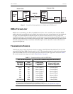
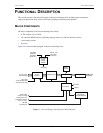
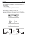
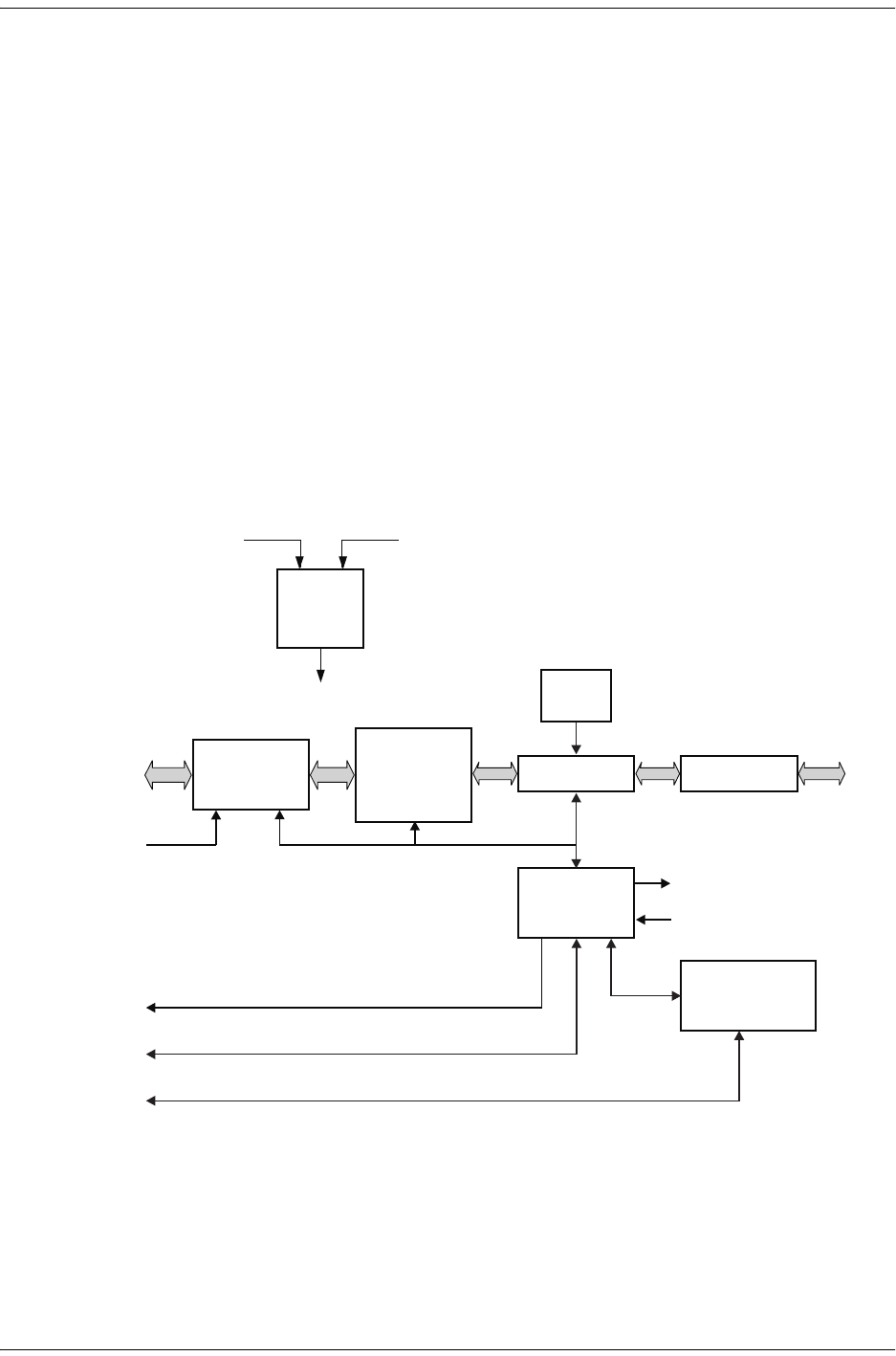
Figure 5 is a functional block diagram of the line and desktop units.
Figure 5. Line and Desktop Unit Functional Block Diagram
On-board
power
supply
module
HDSL framer
Transceiver
Timing
circuits
Line interface
Processor
Ext. clock
from management
unit (UTU-701 only)
+5V, +3.3V
HDSL
loop
-36V to -72V
DC power
(UTU-701)
100-240V
50/60 Hz
AC power
(ETU-751)
Alarm relay
(UTU-701 only)
Control
Status
RS-232
console port
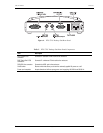
Front panel
control and
console interface
Management unit
backplane interface
(UTU-701 only)
G.703
Interface
75 and 120
DTE Interface
Ω