


700-701-100-02 System Configuration
UTU-701 and ETU-751 List 1 August 9, 2002 25
SYSTEM CONFIGURATION
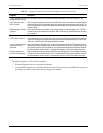
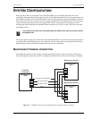
Each line unit provides a system-wide view of the entire HDSL circuit, including the remote unit. After
establishing communication with the remote line card, provisioning information can be set and performance can
be monitored from the local unit. If the HDSL link is down, the only parameters that can be changed are those on
the local line unit. The LTU overwrites any NTU settings when the link is re-established. The LTU also provides
a special lockout feature that prevents users plugged into the NTU console port from changing the circuit
configuration. When enabled, the maintenance terminal connected to an NTU provides a read-only view of the
entire HDSL system.
The line unit option settings are stored in non-volatile RAM (NVRAM). No dip switches or jumpers are required
to configure these options. These options are set from the console screen menus or management unit interface.
Option settings stored in NVRAM are retained if the line unit loses shelf power.
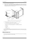
MAINTENANCE TERMINAL CONNECTION
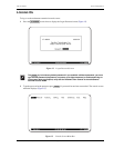
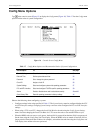
The maintenance terminal (or PC running a terminal emulation program) is used to access the console screen
menus. Through these menus, the system is configured, monitored, tested, and its circuit inventory is displayed.
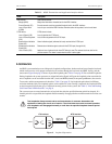
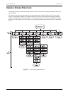
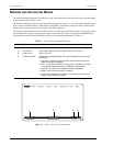
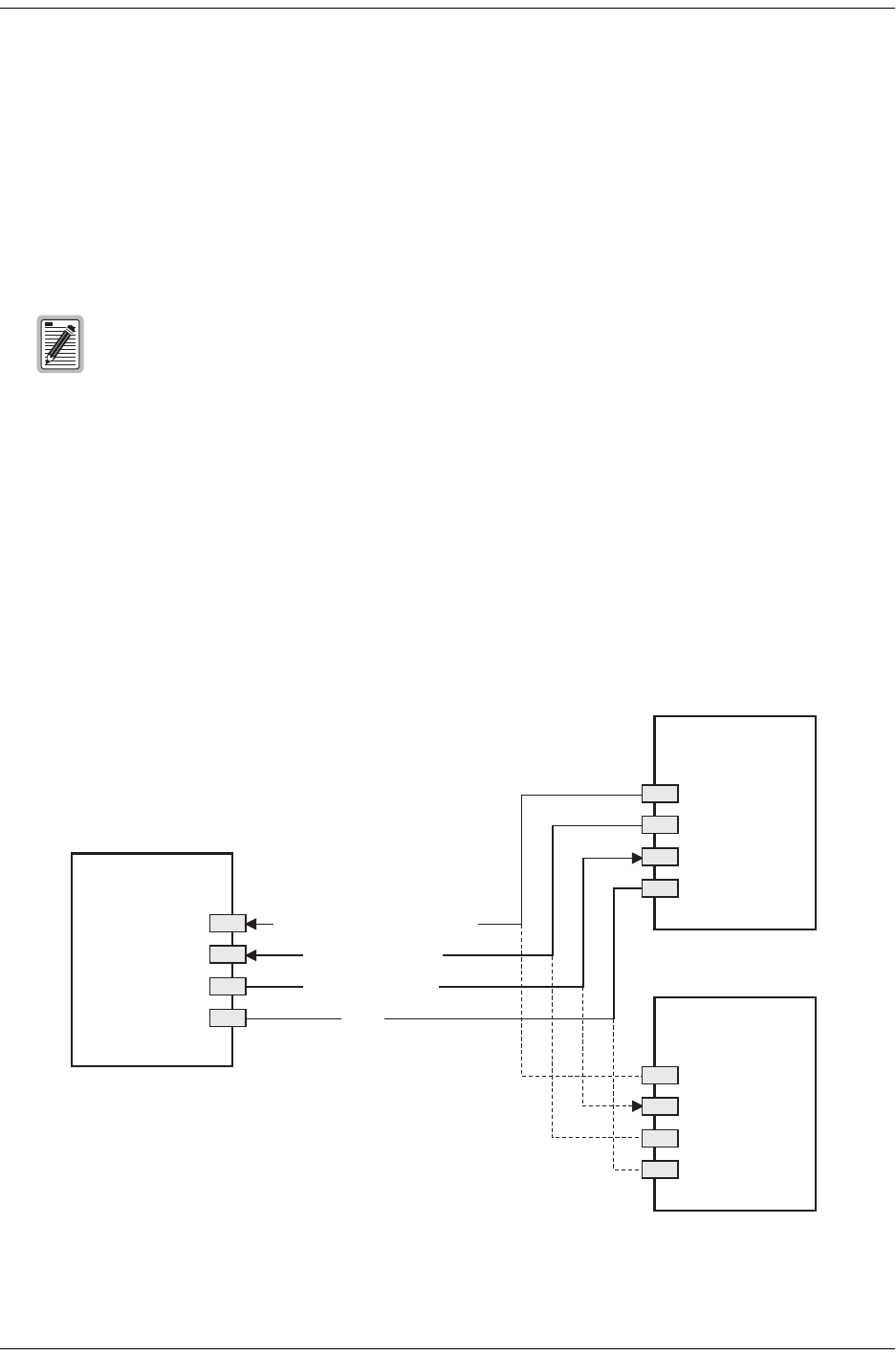
Figure 10. UTU/ETU Console Port and Maintenance Terminal Connector Pinouts
The console screen menus are not available when the HDSL card is under the control of a shelf
management unit.
UTU/ETU
Console port
DB-9 Connector
(DCE)
DTR (Data Terminal Ready)
TD (Transmit Data)
RD (Receive Data)
GND
4
3
2
5
DB-9 Connector
(DTE)
DB-25 Connector
(DTE)
Maintenance terminal
Maintenance terminal
4
3
2
5
20
3
2
7