


www.addonics.com Technical Support (M-F 8:30am - 6:00pm PST) Phone: 408-453-6212 Email: www.addonics.com/support/query/
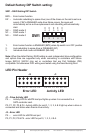
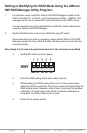
Default factory DIP Switch setting:
SW1 – RAID Setting DIP Switch
BZS – Error buzzer function
EZ – Automatic rebuilding to spare drive (one of the drives on the raid is set as a
spare). If EZ is ENABLED anda drive failure occurs, the spare will
automatically act as a drive replacement and rebuilding will automatically
start.
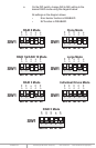
M2 – RAID mode 2
M1 – RAID mode 1
M0 – RAID mode 0
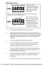
1. Error buzzer function is ENABLED (BZS) when dip switch is in OFF position
2. Auto-rebuilding to spare drive is DISABLED (EZ)
3. Individual drive mode is ENABLED (M0~M2)
Note: When the default factory RAID setting is used, independent drive configuration
and optical drive are supported only when connecting to controllers with Silicon
Image Sil3124, Sil3132 chip set or controllers that are Port Multiplier (PM)
compatible. Simultaneous DVD writing was tested using the Nero Burning Rom.
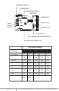
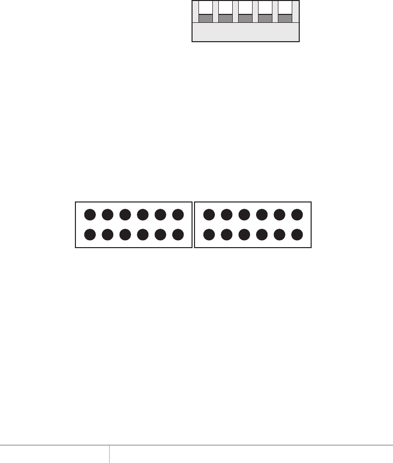
LED Pin Header
J1 – Drive Activity LED
P5 – Activity LED for eSATA host port lights up when it is connected to a
SATA controller card.
P0, P1, P2, P3 & P4 - Activity LEDs for port 0, 1, 2, 3, 4 & 5 light up when a drive is
connected and blinks when there’s drive activity.
J3 – Error LED
P5 – error LED for eSATA host port
P0, P1, P2, P3 & P4 - error LED for port 0, 1, 2, 3, 4 & 5
J3 J1
Error LED Activity LED
P5 P0 P1 P2 P3 P4 P5 P0 P1 P2 P3 P4
1 2 3 4 5
SW1
BZS EZ M2 M1 M0
OFF
OFF
OFF
OFF
OFF